Pressure regulator for a fuel supply unit and method for production of a pressure regulator

a technology of pressure regulator and fuel supply unit, which is applied in the direction of valve housing, machine/engine, operating means/releasing devices, etc., can solve the problems of pressure regulators that are often completely blown, the sealing of the membrane is insufficient, etc., and achieves low manufacturing cost, high degree of stability, and production particularly cost-effective

Active Publication Date: 2010-11-09
NANOTEK INSTR +1
View PDF14 Cites 7 Cited by
  • Summary
  • Abstract
  • Description
  • Claims
  • Application Information

AI Technical Summary

Benefits of technology

[0007]This design enables the membrane to be joined to the annular element with a cohesive material joint. This ensures reliable tightness in particular in the temperature range below 0° C. Settling gaps between the membrane and the annular element, which may result in leakages after a certain operating time of the pressure regulator according to the invention, are likewise reliably avoided. This ensures reliable tightness between the membrane and the annular element.
[0008]In the case of a pressure regulator according to the invention and designed as a throughflow valve, the tightness between the region below the piston and the region above the piston can be further increased if the membrane is welded to the piston.
[0009]Flow through the piston above the designated pressure can be ensured in a simple manner, according to another advantageous development of the invention, if the membrane has a recess for a valve seat arranged in the piston.
[0012]According to another advantageous development of the invention, the membrane, the annular element and the piston have a particularly high degree of stability if the plastic has inserts of glass fibers.
[0013]The welded joint of the membrane can be produced particularly cost-effectively, according to another advantageous development of the invention, if the membrane or the component to be welded to the membrane is manufactured from a material permeable to a laser beam and the respectively other component is manufactured from a material impermeable to a laser beam. This design enables the membrane to be welded by means of the laser beam. This results in particularly low manufacturing costs in particular in series manufacturing of the pressure regulator according to the invention. In addition, the manufacturing can be automated.
[0016]By this means, settling gaps which arise during the flanging operation, as in the case of the known annular element, are reliably avoided. Owing to the invention, the membrane is joined to the annular element with a cohesive material joint. This leads to particularly reliable sealing of the membrane in relation to the annular element in particular in the range below 0° C. In the case of a pressure regulator designed as a straight-way valve, the piston can be welded to the membrane in an analogous manner.

Problems solved by technology

A drawback of the known pressure regulator is that the sealing of the membrane is insufficient, in particular in the temperature range below 0° C., in order to keep the designated pressure at which the pressure regulator is to open within an exacting tolerance range.
The pressure regulator may frequently fail completely due to leakages at the outer edge.

Method used


Image

  • Pressure regulator for a fuel supply unit and method for production of a pressure regulator
  • Pressure regulator for a fuel supply unit and method for production of a pressure regulator
  • Pressure regulator for a fuel supply unit and method for production of a pressure regulator

Examples


Embodiment Construction

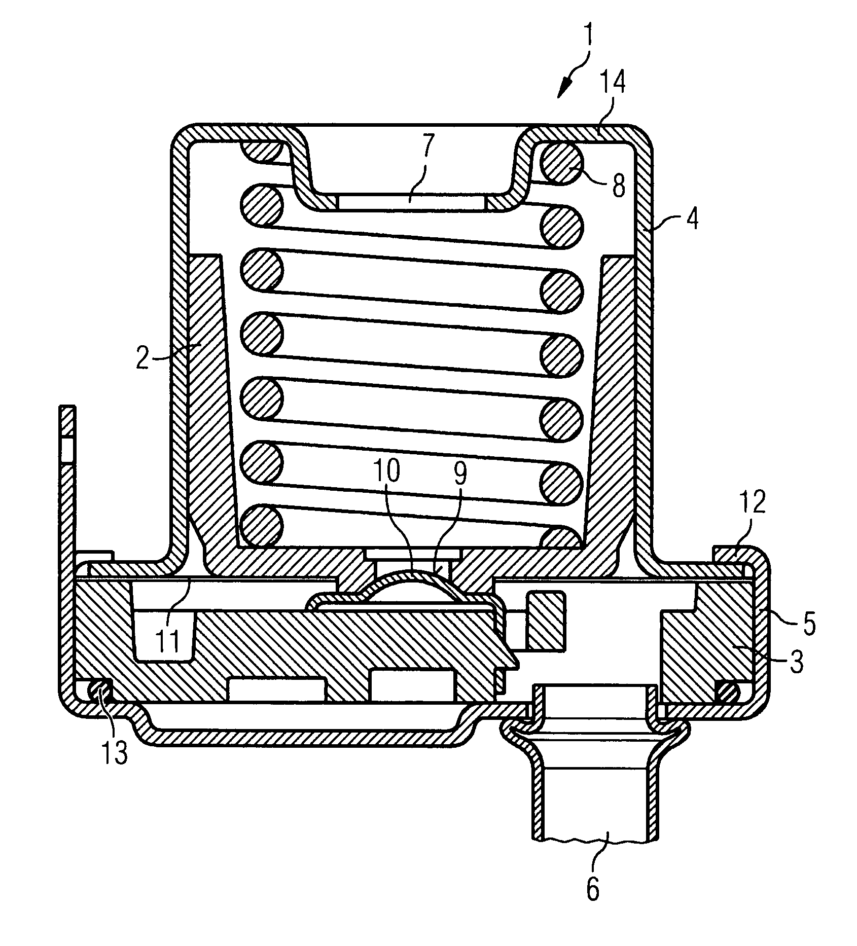
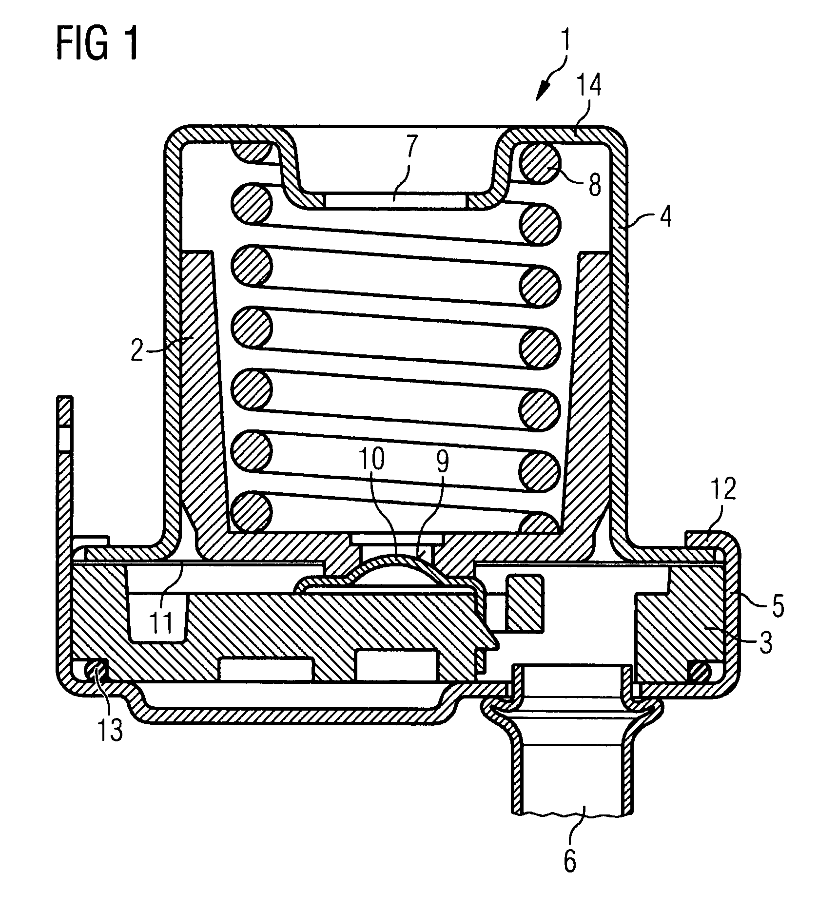
[0021]FIG. 1 shows a pressure regulator according to the invention and designed as a throughflow valve with a housing 1 and a piston 2 arranged displaceably in the housing 1. The pressure regulator serves to limit a maximum pressure in a forward flow line (not illustrated) of a fuel tank of a motor vehicle. The housing 1 has two housing parts 4, 5 which are kept at a distance by an annular element 3. The pressure regulator has a connection 6 for a pressure line, and an outlet 7. The piston 2 is prestressed with a valve seat 9 against a valve body 10 by means of a spring 8 designed as a spiral spring.

[0022]A membrane 11 joined to the annular element 3 and the piston 2 seals the region below the piston 2 from the region above the piston 2. This ensures that, at a pressure in the connection 6, the piston 2 is loaded counter to the force of the spring 8 and, above a designated pressure, the piston 2 is moved such that the valve seat 9 lifts off from the valve body 10. Above the designat...


PUM

PropertyMeasurementUnit
temperatureaaaaaaaaaa
pressureaaaaaaaaaa
plasticaaaaaaaaaa

Abstract

Disclosed is a pressure regulator for a fuel supply unit of a motor vehicle and method for production of a pressure regulator. The pressure regulator comprises a valve for producing a joining of a connection to an outlet above a designated pressure in the connection, a movable piston and a membrane, which is held on a fixed annular element, for sealing the piston in relation to the annular element, characterized in that the membrane is welded to the annular element.

Description

BACKGROUND OF THE INVENTION[0001]Pressure regulator for a fuel supply unit and method for production of a pressure regulator[0002]The invention relates to a pressure regulator for a fuel supply unit of a motor vehicle, with a valve for producing a joining of a connection to an outlet above a designated pressure in the connection, with a movable piston and with a membrane, which is held on a fixed annular element, for sealing the piston in relation to the annular element. Furthermore, the invention relates to a method for production of a pressure regulator for a fuel supply unit of a motor vehicle, in which a piston of a valve is joined to a fixed annular element in a sealing manner via a membrane.[0003]Pressure regulators of this type are frequently used in motor vehicles today to regulate a pressure in a forward flow line leading to an internal combustion engine, and are known from practice. The membrane is clamped between two annular elements of the housing and separates the regio...

Claims


Application Information

Patent Timeline
Patent Type & Authority Patents(United States)
IPC IPC(8): G05D16/10F16K27/10
CPCF02M69/54Y10T29/494Y10T137/7834Y10T137/7836Y10T137/7793F02M69/00
Inventor DIESING, DETLEVECK, KARLSCHMID, RENE
Owner NANOTEK INSTR
Why Eureka
Try Eureka