Two-Part high voltage vacuum feed through for an electron tube

Active Publication Date: 2015-11-12
TRIBO LABS +1
View PDF7 Cites 4 Cited by
  • Summary
  • Abstract
  • Description
  • Claims
  • Application Information

AI Technical Summary

Benefits of technology

[0038]c) mounting the front part of the anode to the rear part. The inventive procedure guarantees tightness of the vacuum feed through with great reliability. The production method is also very flexible with respect to the target material of the front part.
[0039]In a preferred variant of the inventive method, the front part is mounted to the rear part in step c) through placing on top and shrinking. This provides a high-strength connection between the front and rear parts of the anode without solder or additional connecting means, in particular, without any problems after step b).
[0040]In another advantageous vari

Problems solved by technology

However, copper and ceramic materials such as aluminium nitride have quite different thermal expansion coefficients such that, during soldering or also due to load (and heating) during operation, large mechanical stress may be generated which can result in that the soldering joints leak.
The X-ray tube is then useless.
The production of elastic claws on the anode is very complex and vacuum-tight soldering to the ceramic insulating body is much more complicated in comparison with an anode having a smooth outer wall.
Another

Method used


Image

  • Two-Part high voltage vacuum feed through for an electron tube
  • Two-Part high voltage vacuum feed through for an electron tube
  • Two-Part high voltage vacuum feed through for an electron tube

Examples


Example

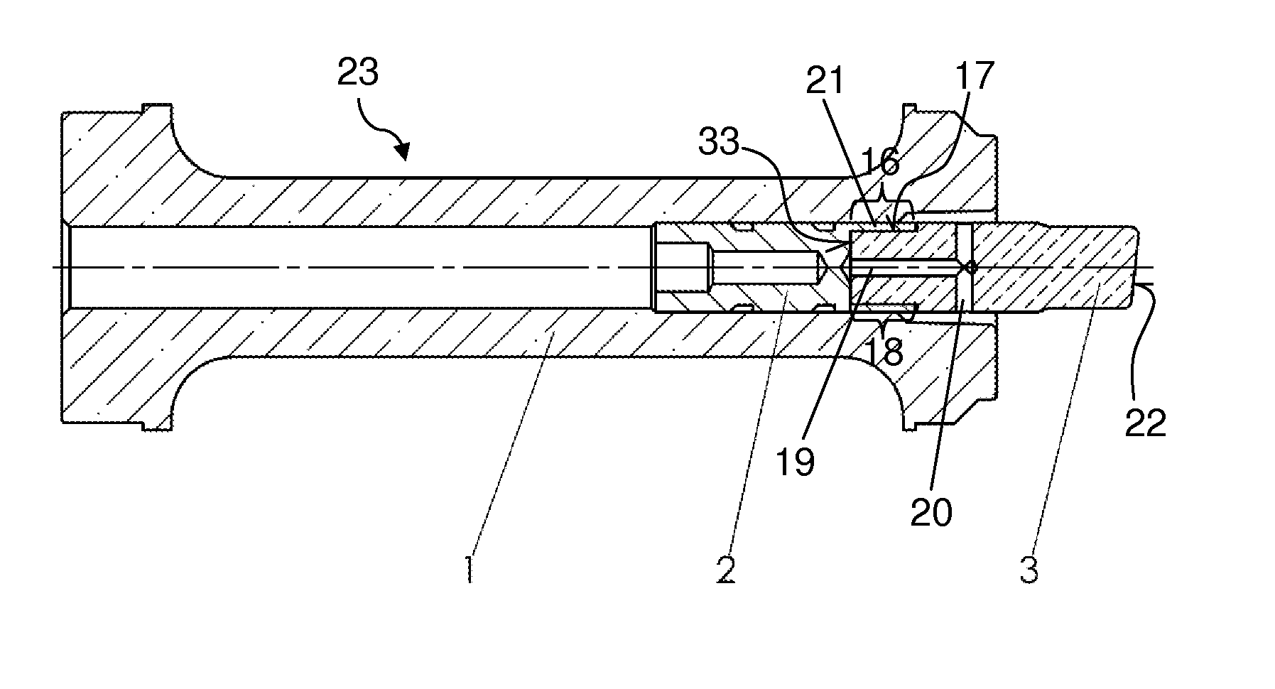
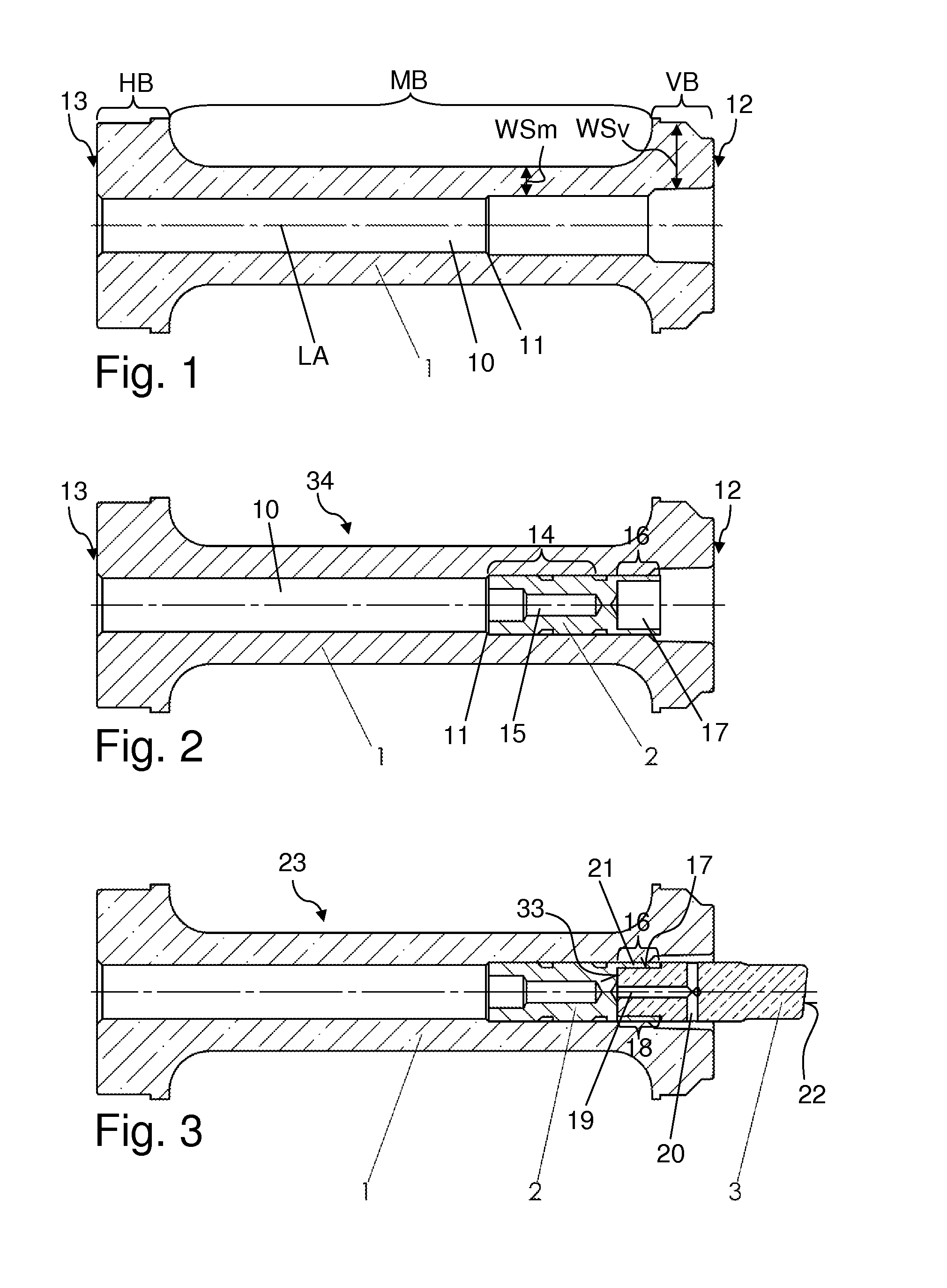
[0052]FIGS. 1 through 3 show the production of an inventive high voltage vacuum feed through in different chronologically successive stages.

[0053]A ceramic insulating body 1 is initially produced or provided, cf. FIG. 1. In the present case, the insulating body 1 is produced from aluminium oxide ceramic material, e.g. through slip casting or other conventional forming technologies, followed by sintering. If desired or required, the Al2O3 ceramic material may contain sintering aids or other additives for optimizing the production process or the quality of the sintered ceramic material in a manner known per se.

[0054]The insulating body 1 is substantially configured to be tubular and has, in particular, a continuous hollow space 10 that extends in a longitudinal direction (cf. longitudinal axis LA) similar to a bore. The insulating body 1 is rotationally symmetrical with respect to the longitudinal axis LA in this case. The hollow space 10 has a step 11 that serves as a stop for a rear...


PUM


Abstract

A high voltage vacuum feed through (23) for an electron tube (25) has an anode (28) and an insulating body (1) of ceramic material, the insulating body (1) having a continuous hollow space (10). The anode (28) has a rear part (2) and a front part (3) mounted thereto. The rear part (2) consists of a first metallic material, having a thermal expansion coefficient corresponding to a thermal expansion coefficient of the ceramic material. The rear part (2) is arranged in the hollow space (10) of the insulating body (1) and is soldered into the insulating body (1) in a vacuum-tight fashion. The front part (3) has a second metallic material whose heat conductivity is larger than that of the first metallic material. The high voltage vacuum feed through reliably remains vacuum-tight during operation and can be easily provided with different target materials.

Description

[0001]This application claims Paris convention priority from DE 10 2014 208 729.5 filed May 9, 2014 the entire disclosure of which is hereby incorporated by reference.BACKGROUND OF THE INVENTION[0002]The invention concerns a high voltage vacuum feed through for an electron tube, in particular, for a solid anode X-ray tube, comprising[0003]an insulating body of ceramic material, wherein the insulating body has a continuous hollow space,[0004]and an anode, wherein a rear end of the anode is arranged in the hollow space of the insulating body and seals the hollow space in a vacuum-tight fashion.[0005]A vacuum feed through of this type is disclosed e.g. in DE 10 2009 017 924 A1.[0006]X-ray radiation is used in various ways in instrumental analysis or also for producing image recordings of human and animal patients in medicine. X-ray radiation is typically generated in an X-ray tube through emission of electrons from an electrically heated electron emitter and acceleration of the electro...

Claims


Application Information

Patent Timeline
IPC IPC(8): H01J35/12H01J9/24H01J9/14H01J35/16
CPCH01J35/12H01J9/14H01J9/24H01J35/16H01J2235/0233H01J35/13
Inventor HANS, KARL
Owner TRIBO LABS
Why Eureka
Try Eureka