
Charging coupling and charging coupling arrangement for a motor vehicle, and motor vehicle

a charging coupling and motor vehicle technology, applied in the direction of charging stations, charging device connections, transportation and packaging, etc., can solve the problem that the charging plug cannot be incorrectly pulled out of the receiving section, and achieve the effect of reliably locking the charging plug in the charging position and preventing unauthorized and/or incorrect removal

Active Publication Date: 2015-02-10
DR ING H C F PORSCHE AG
View PDF28 Cites 36 Cited by
  • Summary
  • Abstract
  • Description
  • Claims
  • Application Information

AI Technical Summary

Benefits of technology

[0011]The invention relates to a charging coupling for a motor vehicle that is operated at least partially electrically. The charging coupling has a receiving device with a receiving section for receiving a charging plug. The charging coupling also has a locking device with a locking section that can be displaced into the receiving section approximately perpendicularly to an introduction direction of the charging plug into the receiving section, so that the charging plug can be locked in the receiving device in a charging position. As a result, the locking section reliably locks the charging plug in the charging position and prevents unauthorized and / or incorrect removal from the receiving section.
[0012]The receiving section preferably cylindrical and hence can be produced simply and inexpensively, thereby reducing the production costs for the charging coupling.
[0013]The locking section preferably is displaced into the receiving section in a direction approximately perpendicular to a center axis of said receiving section. Thus, the locking section achieves a very effective locking of the charging plug in the receiving section and prevents the charging plug from being pulled off unintentionally.

Problems solved by technology

As a result, the charging plug cannot be pulled incorrectly out of the receiving section.

Method used


Image

  • Charging coupling and charging coupling arrangement for a motor vehicle, and motor vehicle
  • Charging coupling and charging coupling arrangement for a motor vehicle, and motor vehicle
  • Charging coupling and charging coupling arrangement for a motor vehicle, and motor vehicle

Examples


Embodiment Construction

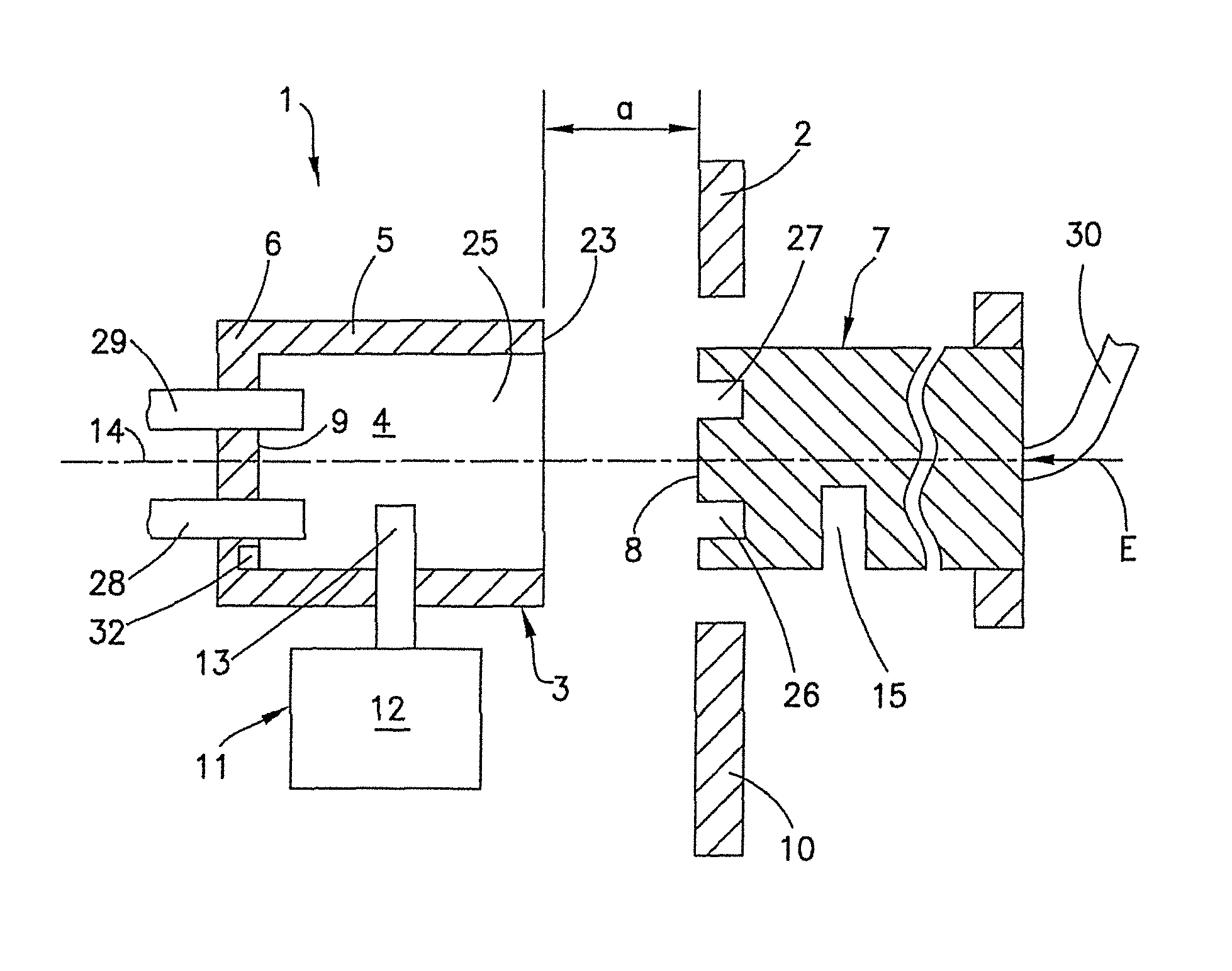
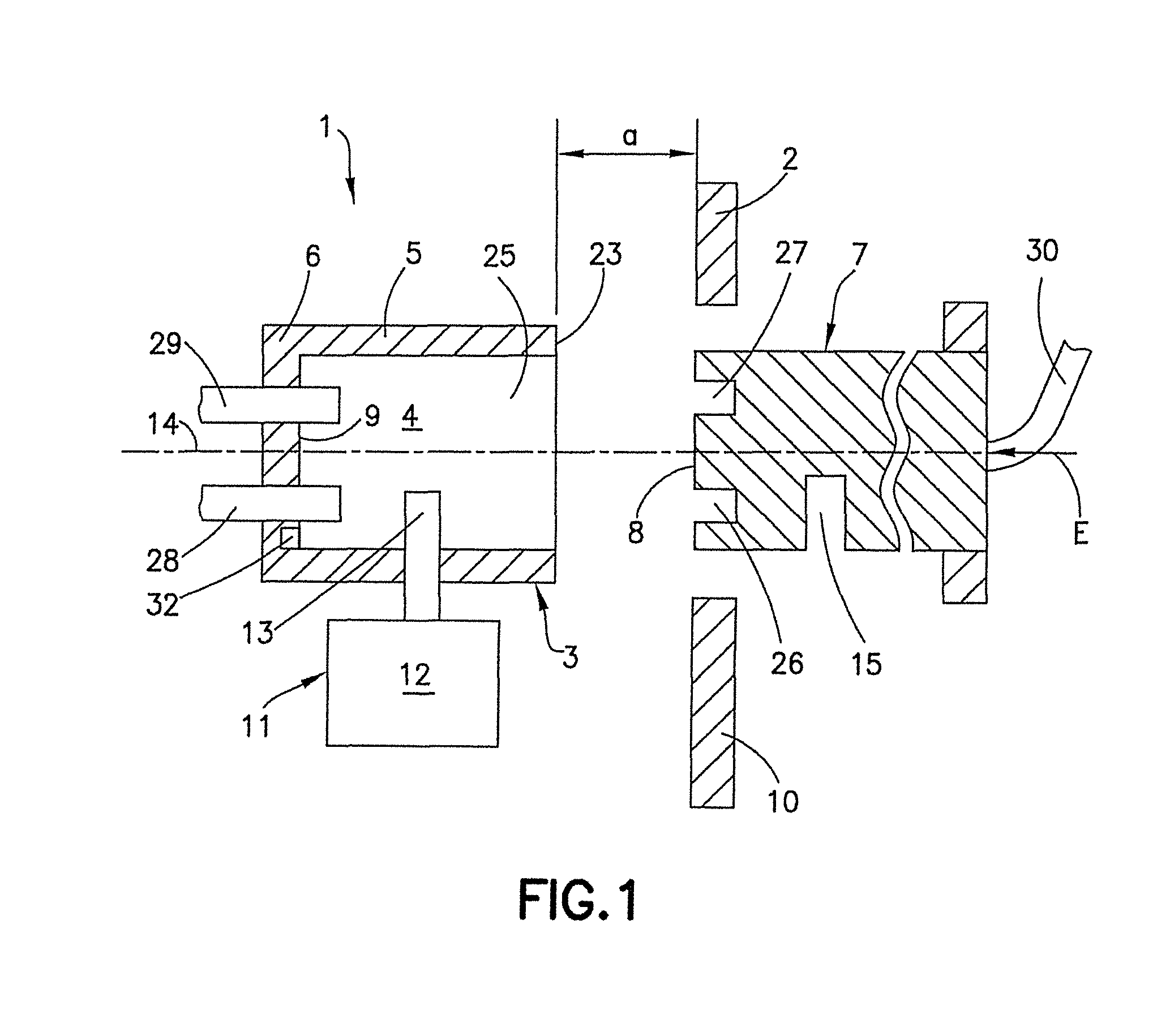
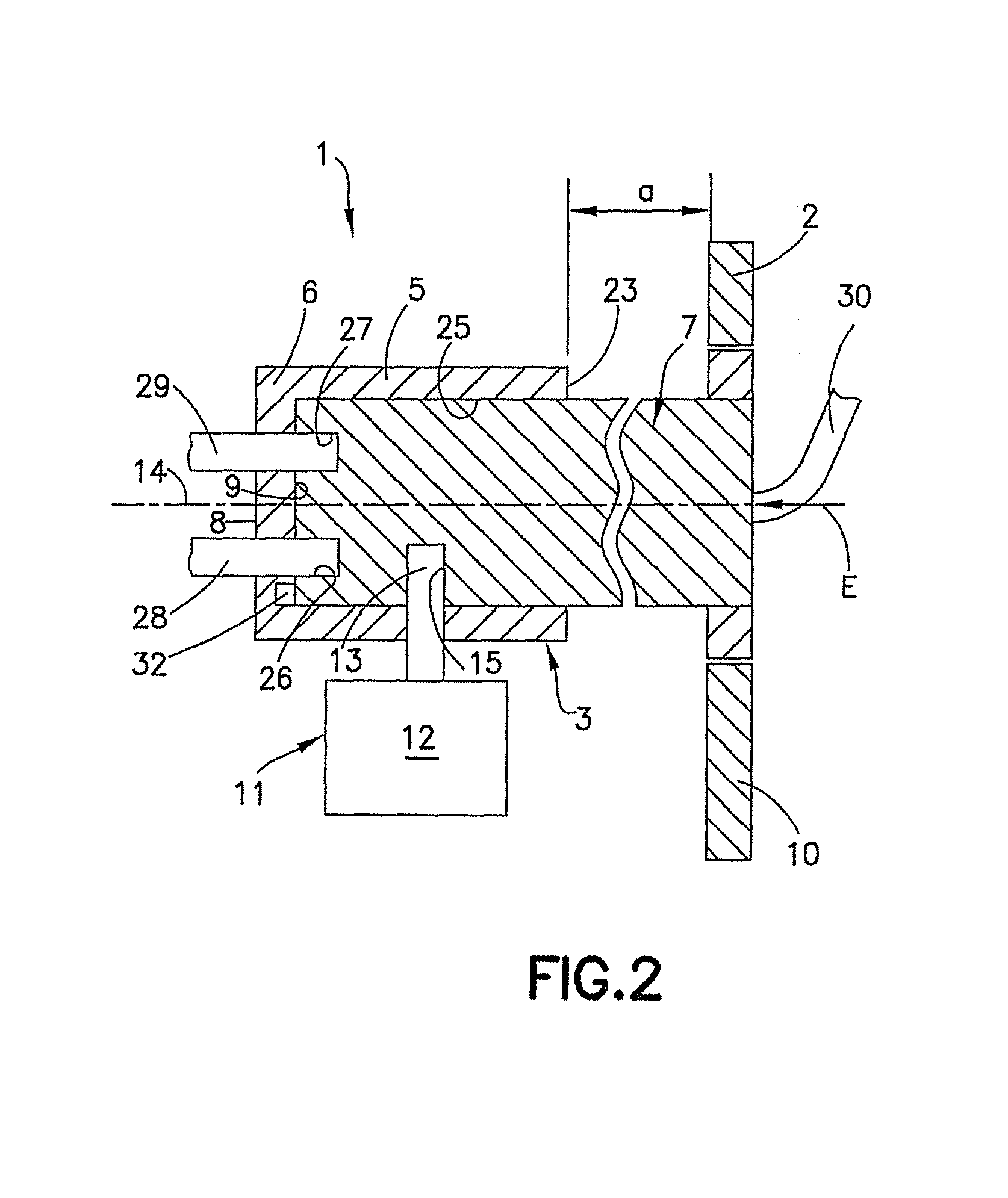
[0028]FIGS. 1 to 3 show a charging coupling 1 for a motor vehicle 2. The motor vehicle 2 is configured as a purely electrically operated motor vehicle or as a plug-in hybrid motor vehicle.

[0029]The charging coupling 1 has a receiving device 3 that functions as a charging socket of the motor vehicle 2. The receiving device 3 has a hollow receiving section 4 in the form of a cavity defined by a side wall 5, an end wall 6 that is closed at least in sections and an opening 25 that faces away from the end wall 6. The receiving section 4 preferably is cylindrical, but can be block-shaped, and is configured so that a charging plug 7 can be inserted through the opening 25 of the receiving device and into the receiving section 4.

[0030]The charging plug 7 is configured complementary to the receiving section 4 of the receiving device 3. In particular, the charging plug 7 has contact elements 26, 27 that can be brought into an electrical operative connection with corresponding mating contact el...


PUM


Abstract

A charging coupling (1) for a motor vehicle (2) has a receiving device (3) with a receiving section (4) for receiving a charging plug (7) and a locking device (11) having a locking section (13) that can be displaced into the receiving section (4) approximately perpendicularly with respect to an introduction direction (E) of the charging plug (7) into the receiving section (4) for locking the charging plug (7) in the receiving device (3) in a charging position. A cover (16) having a sealing device (21) is provided for closing the receiving section (4) in a dust-tight and water-tight manner when the charging plug (7) is removed from the receiving section (4).

Description

CROSS REFERENCE TO RELATED APPLICATION[0001]This application claims priority under 35 USC 119 to German Patent Appl. No. 10 2011 052 078.3 filed on Jul. 22, 2011, the entire disclosure of which is incorporated herein by reference.BACKGROUND OF THE INVENTION[0002]1. Field of the Invention[0003]The invention relates to a charging coupling and to a charging coupling arrangement for a motor vehicle that is operated at least partially electrically, and to a motor vehicle that is operated at least partially electrically, having a charging coupling of this type or having a charging coupling arrangement of this type.[0004]2. Description of the Related Art[0005]Plug-in hybrid vehicles have an energy store that can be charged via an external power network, for example, in addition to recuperation operation. To this end, the vehicle must have a charging coupling, such as a charging socket that can be connected to an external charging cable.[0006]WO 2010 / 143040 A1 proposes a charging socket of ...

Claims


Application Information

Patent Timeline
Patent Type & Authority Patents(United States)
IPC IPC(8): H01R13/625H01R13/447B60L11/18H01R13/639
CPCH01R13/639B60L11/1818B60L2270/32B60L2270/34Y02T10/7088Y02T10/7005Y02T90/121Y02T90/14Y02T10/7072B60L53/16Y02T10/70Y02T90/12
Inventor MEYER-EBELING, JOERG
Owner DR ING H C F PORSCHE AG
Learn More