X-ray stress measurement method and apparatus

a stress measurement and stress technology, applied in the direction of force measurement, material analysis using radiation diffraction, instruments, etc., can solve the problems of further longer measurement time and long measurement time, and achieve the effect of speeding up stress measurement and performing rapid measuremen

Active Publication Date: 2015-02-10
RIGAKU CORP
View PDF10 Cites 5 Cited by
  • Summary
  • Abstract
  • Description
  • Claims
  • Application Information

AI Technical Summary

Benefits of technology

[0010]Furthermore, the present invention has another object to further speed up a measurement of the stress gradient in a depth direction of the sample.
[0037]As described above, according to the present invention, information of X-ray diffractions associated with plural Ψ angles can be simultaneously obtained, and thus speed-up of the stress measurement can be implemented.

Problems solved by technology

However, in order to determine the gradient according to the 2θ-sin2 Ψ method, it is required to vary the Ψ angle at least two times and measure the position value of the diffraction angle 2θ every time the Ψ angle is varied, so that this method requires a long measurement time.
Therefore, this method has a problem that the measurement time is further longer.

Method used


Image

  • X-ray stress measurement method and apparatus
  • X-ray stress measurement method and apparatus
  • X-ray stress measurement method and apparatus

Examples


Embodiment Construction

[0057]An embodiment according to the present invention will be described hereunder with reference to the drawings.

[Construction of X-ray Stress Measurement Apparatus]

[0058]First, an X-ray stress measurement apparatus according to an embodiment of the present invention will be described with respect to FIGS. 4, 5A and 5B.

[0059]FIG. 4 is a perspective view showing the X-ray stress measurement apparatus according to the embodiment. FIG. 5A is a plan view showing the apparatus shown in FIG. 4, and FIG. 5B is a front view showing an image plate which is used for the apparatus and planarly developed.

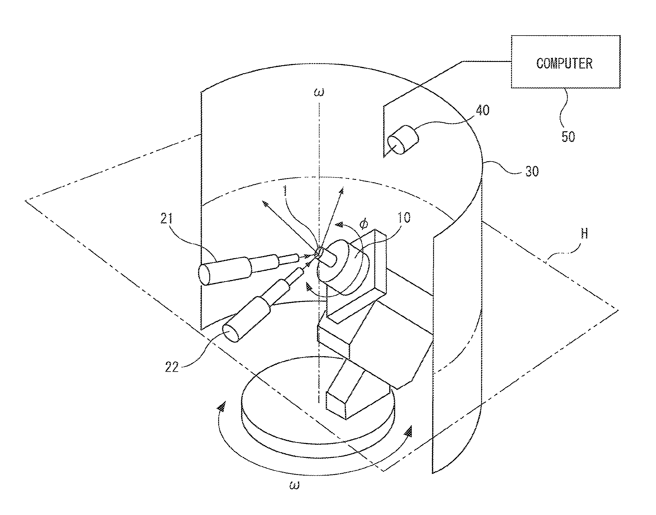
[0060]As shown in FIG. 4, the X-ray stress measurement apparatus has a sample table 10 for holding a sample 1 while the sample 1 is disposed at the tip of the sample table 10, two X-ray sources 21 and 22 for irradiating the surface of the sample 1 with X-ray, an image plate 30 (X-ray detector) for detecting and recording X-ray diffraction diffracted from crystal lattice planes in the sample 1,...


PUM

PropertyMeasurementUnit
stressaaaaaaaaaa
offset angleaaaaaaaaaa
incident anglesaaaaaaaaaa

Abstract

A sample (1) is irradiated with X-rays at different incident angles from plural X-ray sources (21, 22). Attention is focused on a Debye-ring of each X-ray diffraction emitted conically from the sample in association with incident X-ray from each of the X-ray sources (21, 22), and stress in the sample (1) is determined on the basis of information of X-ray diffraction appearing at an intersection point between the Debye-ring of the X-ray diffraction recorded on an image plate (30) and an equatorial plane (H) and information of X-ray diffraction appearing in the neighborhood of the intersection point between the Debye-ring and the equatorial plane (H).

Description

FIELD OF THE INVENTION[0001]The present invention relates to X-ray stress measurement method and apparatus for measuring residual stress accumulated in a sample by using X-ray.BACKGROUND OF THE INVENTION[0002]An X-ray stress measurement method and an X-ray stress measurement apparatus have been broadly known, and the applicant of this application has already proposed plural inventions (see JP-A-08-320264, JP-A-2000-213999, JP-A-2004-93404 and WO2012 / 015046A1). The conventional X-ray stress measurement apparatus generally has one X-ray source mounted therein, and it is configured to irradiate a sample as a measurement target with X-ray from the X-ray source, detect X-ray diffraction from the sample and non-destructively measure stress of the sample on the basis of information of the X-ray diffraction. A method called as “2θ-sin2 Ψ method” is known as such an X-ray stress measurement method as described above.[0003]The 2θ-sin2 Ψ method will be briefly described hereunder.[0004]In FIGS...

Claims


Application Information

Patent Timeline
Patent Type & Authority Patents(United States)
IPC IPC(8): G01N23/20G01L1/25G01N23/207
CPCG01L1/25G01N23/207
Inventor YASUKAWA, SHOICHI
Owner RIGAKU CORP
Why Eureka
Try Eureka