
Voltage and current measuring device

a voltage and current measurement and voltage technology, applied in the field of measurement devices, can solve the problems of high production cost, high cost of conventional multimeters, inefficient related prior art, etc., and achieve the effects of convenient and convenient use, convenient use, and convenient us

Inactive Publication Date: 2013-08-01
ASKEY TECH JIANGSU +1
View PDF9 Cites 0 Cited by
  • Summary
  • Abstract
  • Description
  • Claims
  • Application Information

AI Technical Summary

Benefits of technology

The present invention is a voltage and current measuring device that is simple, integrated, and compact. It allows for simultaneous measurement of voltage and current, and can be expanded for connection to a computer and other peripherals through the test apparatus. This multi-purpose device speeds up measurement processes and reduces production costs.

Problems solved by technology

The related prior art is so limited that the time taken to test any objects under test increases with the quantity thereof Furthermore, the related prior art is so inefficient that, in some circumstances, two or more conventional multimeters are required to test two or more objects under test.
Last but not least, the conventional multimeter is expensive and thus contributes to high production costs.

Method used


Image

  • Voltage and current measuring device
  • Voltage and current measuring device
  • Voltage and current measuring device

Examples


Embodiment Construction

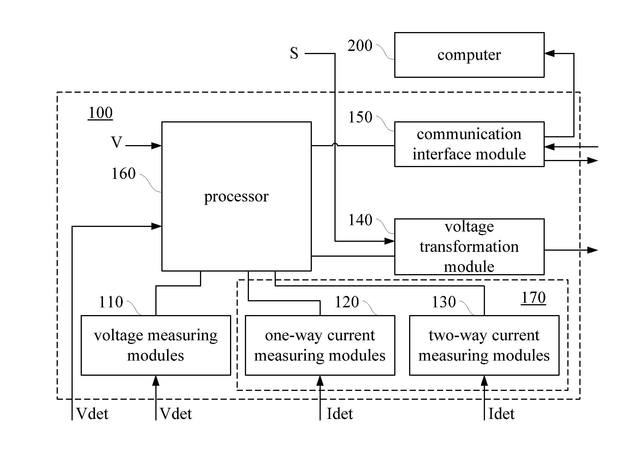
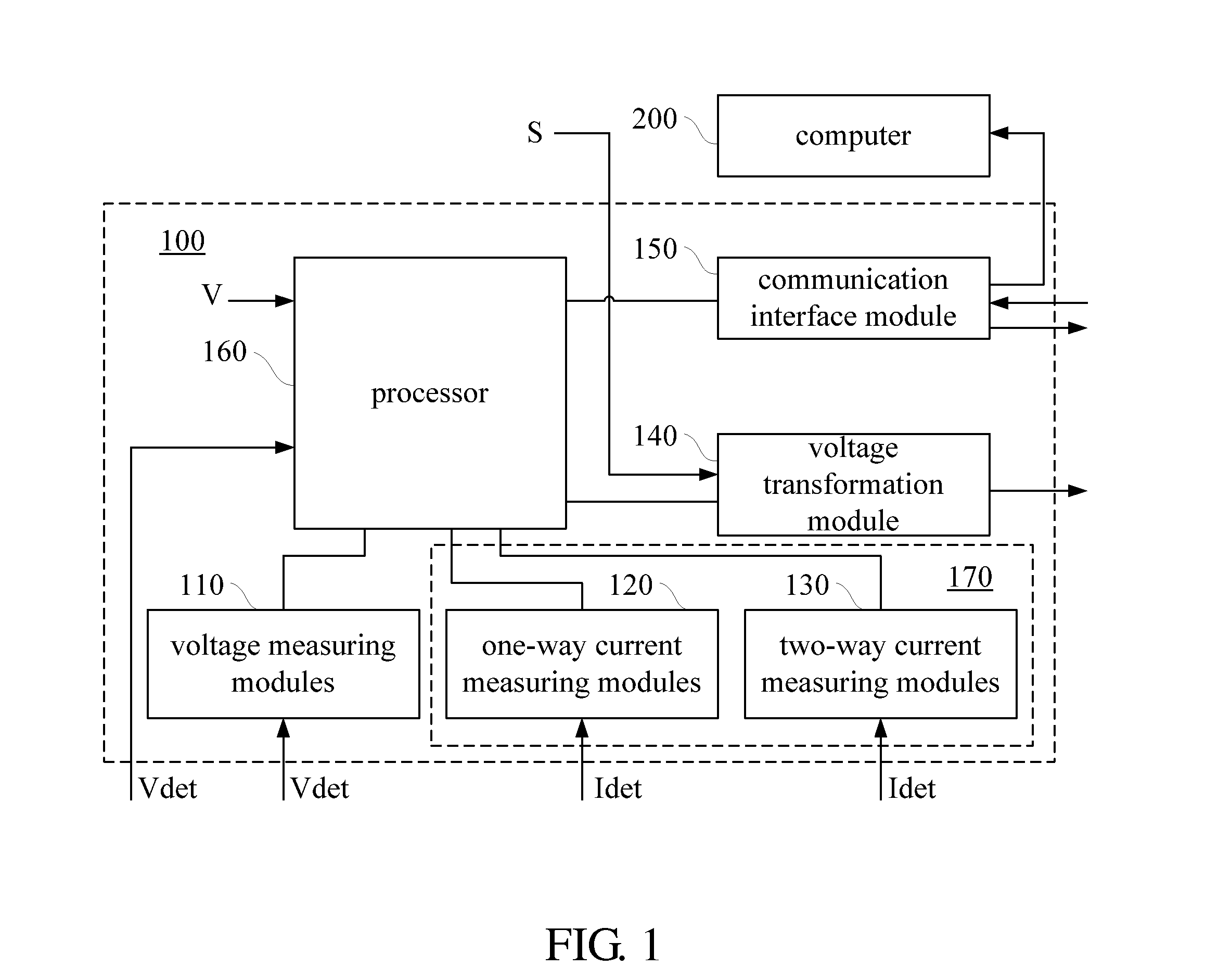
[0021]Referring to FIG. 1, there is shown a functional block diagram of a voltage and current measuring device 100 according to an embodiment of the present invention. The voltage and current measuring device 100 comprises a plurality of voltage measuring modules 110, a voltage transformation module 140, a communication interface module 150, a the processor 160, and a plurality of current measuring modules 170. The voltage and current measuring device 100 receives an external power supply S. The power supply S, coupled with a voltage transformation device (not shown), supplies a required operating voltage to all the components inside the voltage and current measuring device 100. For example, the power supply S supplies the processor 160 with a required preset processor voltage level V. The technical means of converting the power supply into an internal operating voltage of a device is readily understood by persons skilled in the art and thus is not described hereunder for the sake o...


PUM


Abstract

A voltage and current measuring device includes a plurality of voltage measuring modules, a plurality of one-way current measuring modules, a plurality of two-way current measuring modules, a voltage transformation module, a communication interface module, and a processor. The modules are integrated to provide different ways of measuring voltage and current concurrently, enable peripheral expansion, and facilitate power supply. Hence, the device features integration and versatility, speeds up a measurement process, and cuts production costs.

Description

CROSS-REFERENCE TO RELATED APPLICATION[0001]This non-provisional application claims priority under 35 U.S.C. §119(a) on Patent Application No(s). 101103126 filed in Taiwan, R.O.C. on Jan. 31, 2012, the entire contents of which are hereby incorporated by reference.FIELD OF TECHNOLOGY[0002]The present invention relates to measurement devices, and more particularly, to an integrated voltage and current measuring device.BACKGROUND[0003]A conventional multimeter that can be connected to a computer usually has only one test port and can only perform a single test in each instance. Furthermore, when measuring voltage or current, the conventional multimeter uses a constant partial voltage or a constant shunt resistance, thereby allowing no room for changes in the range of measurement.[0004]The related prior art is so limited that the time taken to test any objects under test increases with the quantity thereof Furthermore, the related prior art is so inefficient that, in some circumstances,...

Claims


Application Information

Patent Timeline
Patent Type & Authority Applications(United States)
IPC IPC(8): G06F19/00G01R19/165
CPCG01R15/142G01R19/0084H04Q2209/84H04Q9/00G01R19/0092
Inventor CHENG, WEI-YAOHSIEH, CHING-FENG
Owner ASKEY TECH JIANGSU
Learn More