Surface texture measuring probe and microscope utilizing the same

a surface texture and measuring probe technology, applied in the direction of mechanical roughness/irregularity measurement, measurement devices, instruments, etc., can solve the problems of deteriorating measurement accuracy, measurement may not be speeded up, and natural frequency fc cannot be heightened, so as to enhance the effect of measuring accuracy and speeding up measuremen

Active Publication Date: 2009-09-01
MITUTOYO CORP
View PDF13 Cites 1 Cited by
  • Summary
  • Abstract
  • Description
  • Claims
  • Application Information

AI Technical Summary

Benefits of technology

[0008]An object of the present invention is to provide a surface texture measuring probe allowing measurement to be speeded up while restraining disturbance vibration to enhance measuring accuracy, and a microscope utilizing the surface texture measuring probe.
[0012]And, since the probe head is supported at the center of the inner space of the first and second supporters via the each three beams respectively extending from the equiangular arrangement positions of the first and second supporters of the first and second supporting bodies toward the center, remarkably high frequency can be excited as compared to the ordinary cantilever probe. Accordingly, the vibration can be heightened, and therefore the measurement can be speeded up. To be more specific, when the position of the probe etc. is controlled according to the feedback from the sensor, the probe might be oscillated if the control is performed with the frequency equal to or higher than the natural frequency fc. However, with this configuration, the natural frequency fc can be heightened, thus realizing of heightening the vibration as well as speeding up the measurement.
[0013]Since the surface texture measuring probe has longitudinal vibration, the surface texture measuring probe will not affect on the optical property as compared to having of flexural vibration, namely, the optical axis will not be deviated due to the flexural vibration or the like, thus providing high accurate measurement. And, as shown in FIG. 3, the vibration mode is vertically symmetrical with the center being the node of vibration, so that the vibration can be restrained by the supporting bodies to function as a so-called dynamic vibration absorber.

Problems solved by technology

According to the above-described near-field scanning optical microscope, since the incident light incident on the surface of the sample is scattered by the extremely small probe and the scattered light is received and detected by the objective optical system, disturbance vibration likely affects on the probe, thus extremely deteriorating measurement accuracy.
However, since the cantilever structure anchored by the holder base as the fixed end is employed for the conventional probe, which causes flexural vibration, the natural frequency fc cannot be heightened.
Therefore, the conventional cantilever probe does not allow the response speed to be increased, so that the measurement may not be speeded up.

Method used


Image

  • Surface texture measuring probe and microscope utilizing the same
  • Surface texture measuring probe and microscope utilizing the same
  • Surface texture measuring probe and microscope utilizing the same

Examples


Embodiment Construction

)

[0028]An embodiment of the present invention will be described below with reference to attached drawings.

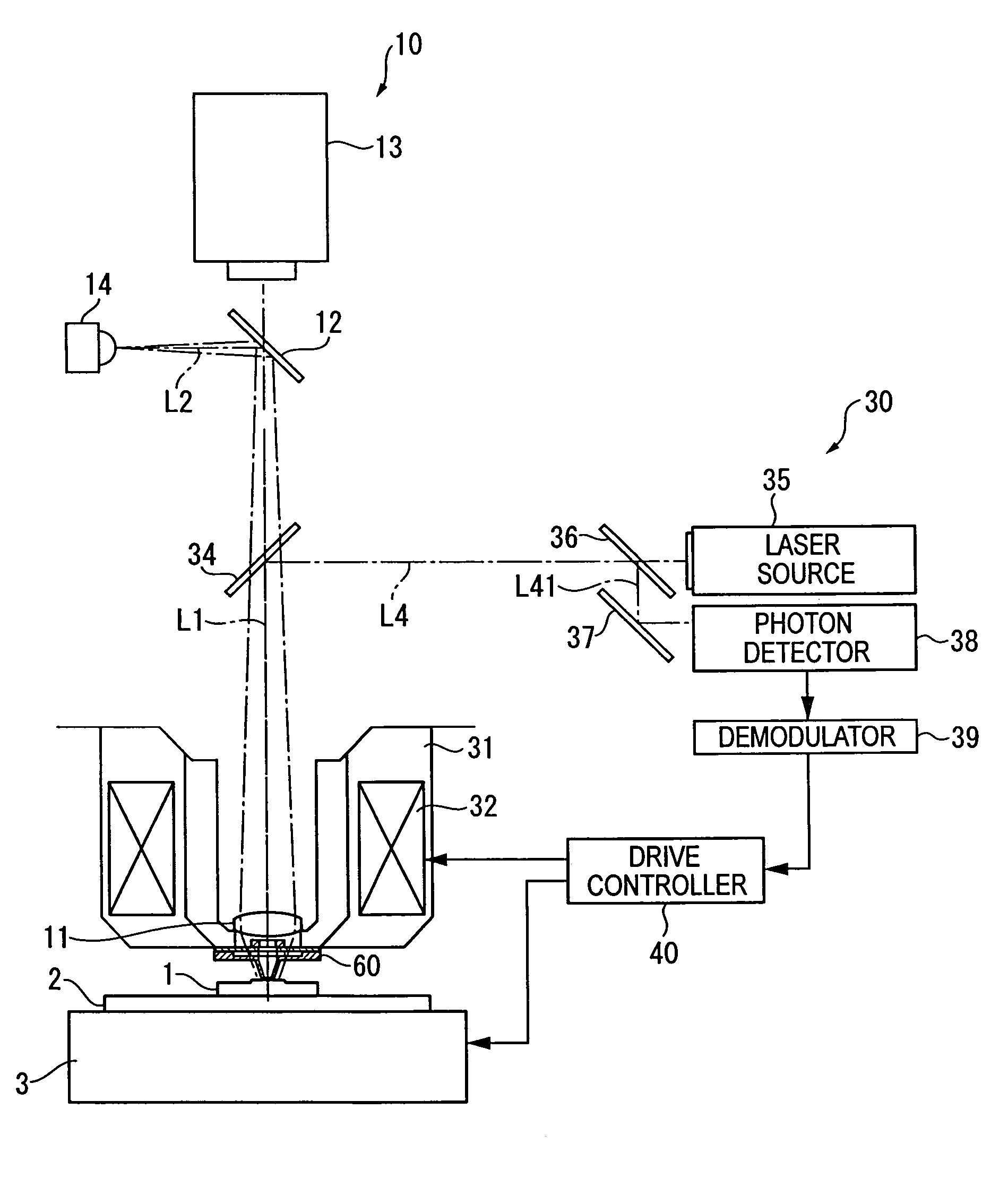
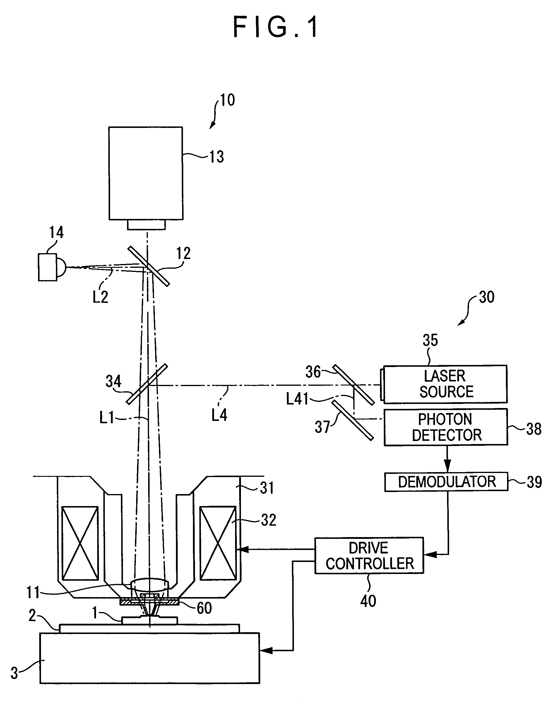
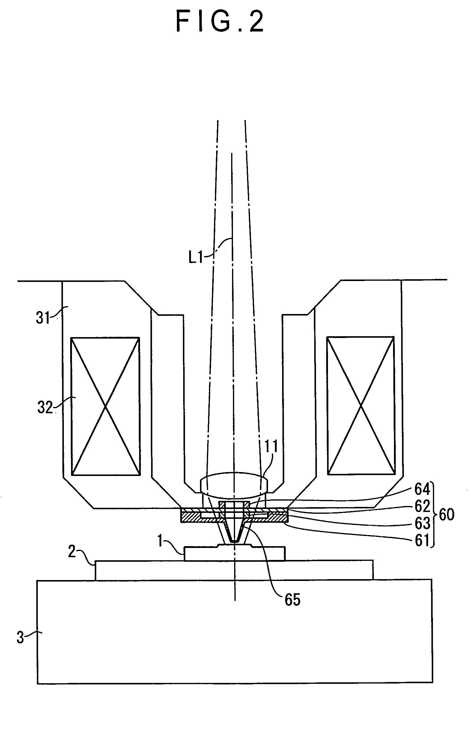
[0029]FIG. 1 shows a near-field scanning optical microscope (NSOM) of the present embodiment. The near-field scanning optical microscope includes a table 2 on which a workpiece 1 is mounted, a relative movement unit 3 that moves the table 2 three-dimensionally (in horizontal, longitudinal, and vertical directions), an optical observation unit 10 that images and observes the workpiece 1 with a camera etc., a near-field measuring unit 30, and a drive controller 40.

[0030]The optical observation unit 10 includes an objective lens 11, a half-mirror 12 arranged on an optical path L1 of the objective lens 11, a CCD camera 13 (image pickup unit) arranged on the optical path L1 of the objective lens 11 to image a light transmitted through the half-mirror 12 (a reflected light from the workpiece 1), and a light source 14 arranged on an optical axis L2 orthogonal to the optical axis L1 of ...


PUM


Abstract

A surface texture measuring probe (60) includes a probe head (65), a first supporting body (61), a second supporting body (62), a piezoelectric element (63) and a balancer (64). The first supporting body includes a first supporter (611) having an inner space, and a plurality of beams (613) respectively extending from equiangular arrangement positions of the first supporter toward the center and supporting the probe head (65) at the tip end thereof. The second supporting body (62) includes a second supporter (621) and a holder (622) supported by a plurality of beams (623) respectively extending from equiangular arrangement positions of the second supporter towards the center. The piezoelectric element (63) is disposed between the probe head and the holder, and formed to vibrate in an axial direction.

Description

BACKGROUND OF THE INVENTION[0001]1. Field of the Invention[0002]The present invention relates to a surface texture measuring probe adaptable to a near-field scanning optical microscope (NSOM), an atomic force microscope (AFM) and a scanning tunneling microscope (STM), as well as a microscope utilizing the surface texture measuring probe.[0003]2. Description of Related Art[0004]An optical microscope has been known as an example of a near-field scanning optical microscope for measuring surface texture of a workpiece utilizing evanescent light (near-field light), which is disclosed in Document 1 (JP-A-2001-165843).[0005]The optical microscope includes a light irradiator that irradiates light on a surface of a sample, a cantilever holding a probe, and an objective optical system that receives scattered light caused by incident light generated at a tip end of the probe. The cantilever is provided with a holder base, which is a fixed end, a probe holder arranged on the holder base to exte...

Claims


Application Information

Patent Timeline
Patent Type & Authority Patents(United States)
IPC IPC(8): G01B5/28G01Q10/04G01Q60/16G01Q60/18G01Q60/22G01Q60/38G01Q70/04G01Q70/10
CPCB82Y20/00B82Y35/00G01Q70/04G01Q60/38G01Q60/22
Inventor HIDAKA, KAZUHIKO
Owner MITUTOYO CORP
Why Eureka
Try Eureka