Eureka AIR delivers breakthrough ideas for toughest innovation challenges, trusted by R&D personnel around the world.

Probe device

a technology of probe device and probe body, which is applied in the direction of mechanical measurement arrangement, mechanical roughness/irregularity measurement, instruments, etc., can solve the problems of large amount of time required and difficulty in image the local electronic structure of the sample, and achieve the effect of speeding up the measurement of charge-transfer for

Inactive Publication Date: 2005-06-30
OSAKA UNIV
View PDF22 Cites 2 Cited by
  • Summary
  • Abstract
  • Description
  • Claims
  • Application Information

AI Technical Summary

Benefits of technology

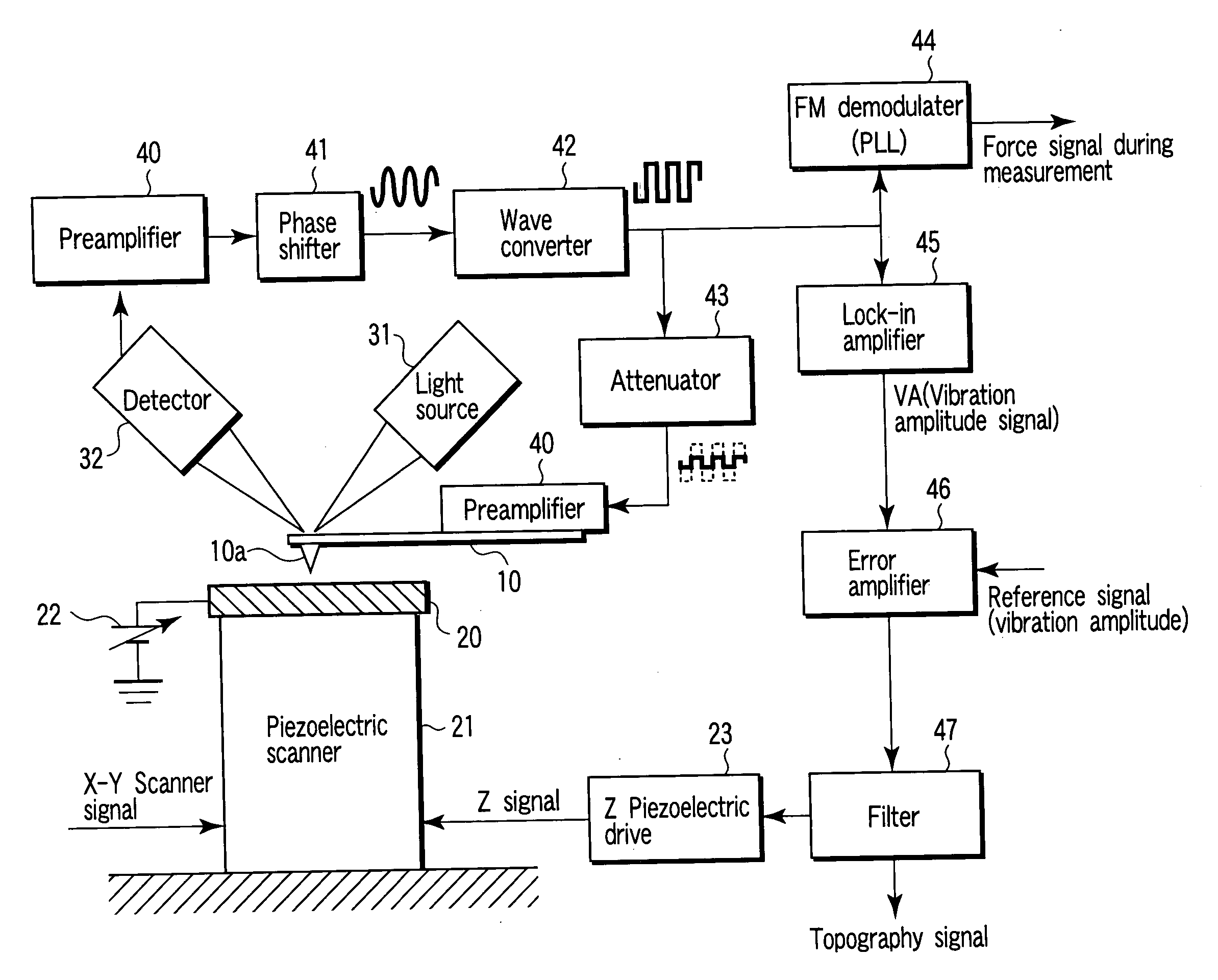
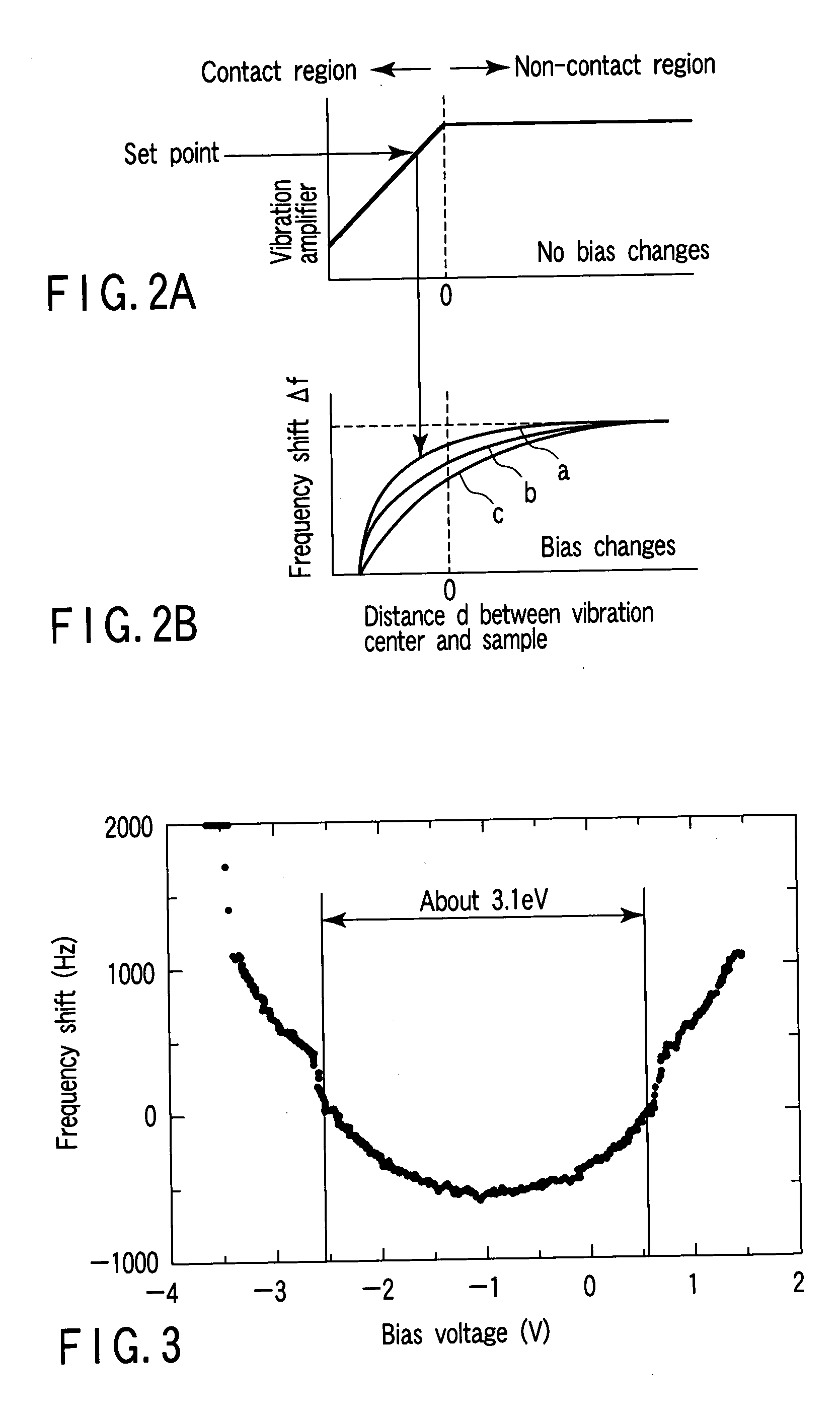
[0015] Thus, according to the present invention, a cantilever which is an AFM probe is oscillated by self-excitation, and a feedback control of tip-sample distance is made based on a vibration amplitude value of the cantilever, whereby an electrostatic force between a probe and a sample is detected under a changed bias condition while an interval between the probe and a surface is constantly controlled. In this case, a force is detected by a deviation (i.e., a frequency shift) of a resonance frequency of the self-excited cantilever oscillation, and bias dependency of this frequency shift is measured. The measurement result reflects the electronic state of the sample, and the force scale changes according to the electronic state of the sample, thus making it possible to measure a local density of states of the sample. In this case, each force curve measurement in the existing technique corresponds to one period of the cantilever which vibrates in the invention, thus significantly speeding up measurement of the charge-transfer force.
[0019] As described above, according to the invention, even in the case of a sample including an insulator, a charge-transfer force can be evaluated at a high speed and while locally controlling an interval between the probe and the sample. Thus, the present invention is very effective for measurement of a local electronic state for a device structure in nano-scale orders.

Problems solved by technology

Therefore, in order to measure the electronic state of the sample, a tremendously large amount of time is required because a respective one of the measurement points must be analyzed from each force curve.
Thus, it has been also difficult to image a local electronic structure of the sample.

Method used


Image

  • Probe device
  • Probe device
  • Probe device

Examples


Embodiment Construction

[0025] Hereinafter, an embodiment of the present invention will be described with reference to the accompanying drawings.

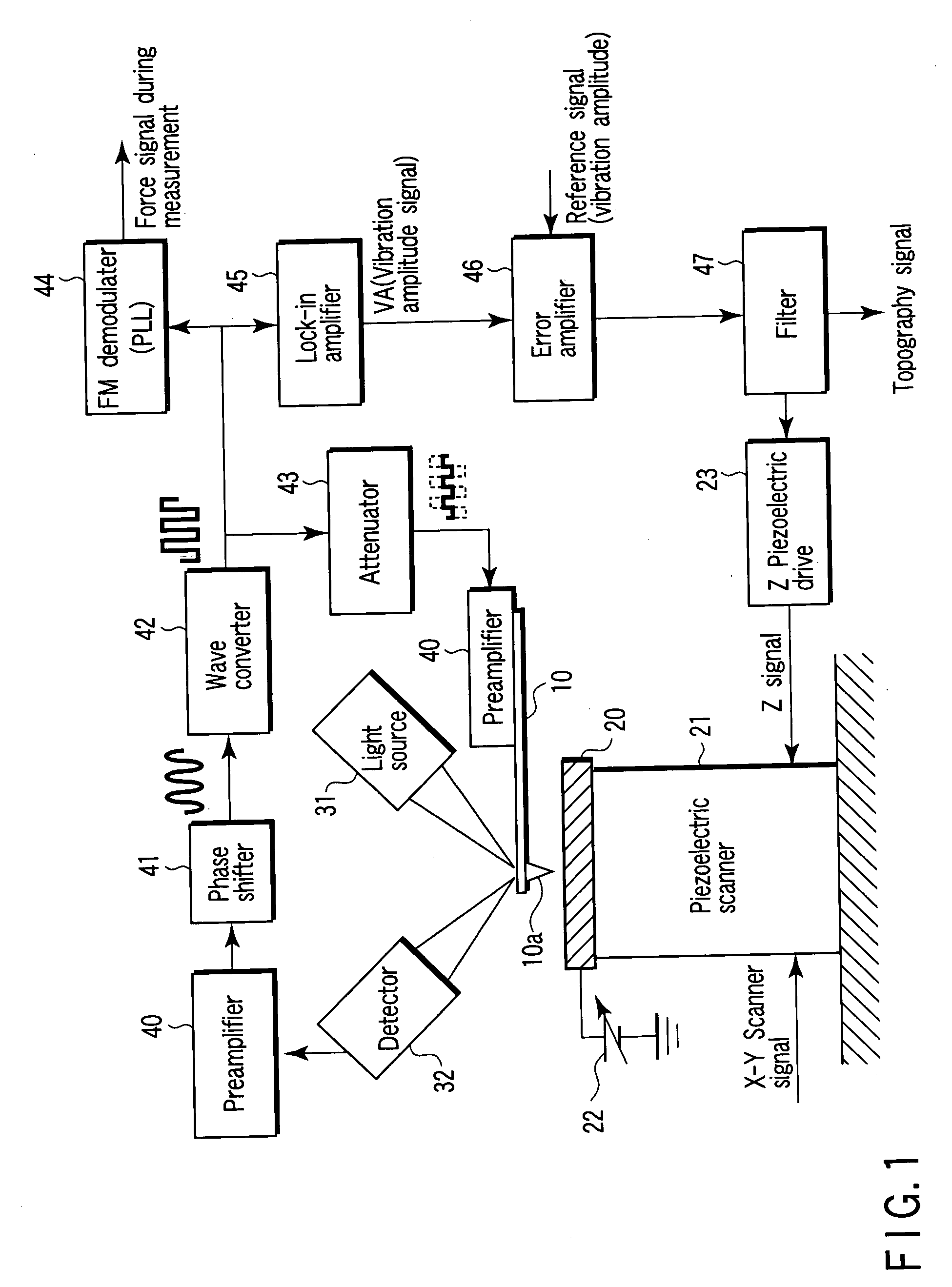
[0026]FIG. 1 is a diagram showing a general configuration of a probe device according to an embodiment of the present invention. In the following description, the probe device will be described by way of example of a generally used atomic force microscope.

[0027] As an atomic force microscope (AFM), there is utilized an AFM using a conductive cantilever 10 having a probe 10a. As shown in FIG. 1, at a position opposed to the probe 10a, a sample 20 is allocated on a piezoelectric scanner 21 so as to be movable on three axes. In addition, the sample 20 can be applied with a desired voltage by means of a bias 22 at which the applied voltage is variable. In the present specification, although an embodiment for applying a bias to a sample is described, such a bias may be applied to a probe.

[0028] The piezoelectric scanner 21 can be moved along an X-Y plane by an X-Y s...


PUM

PropertyMeasurementUnit
band gapaaaaaaaaaa
band gapaaaaaaaaaa
band gapaaaaaaaaaa

Abstract

A probe device comprises a cantilever comprising a probe allocated to be opposed to a surface of a sample, means for feeding back a vibration amplitude value of the cantilever, thereby self-exciting and vibrating the cantilever at a predetermined frequency, means for applying a bias to the sample or the probe, and means for measuring a frequency shift caused by a charge-transfer force which acts between the cantilever and the sample.

Description

CROSS-REFERENCE TO RELATED APPLICATIONS [0001] This is a Continuation Application of PCT Application No. PCT / JP03 / 03728, filed Mar. 26, 2003, which was published under PCT Article 21(2) in Japanese.[0002] This application is based upon and claims the benefit of priority from prior Japanese Patent Application No. 2002-245810, filed Aug. 26, 2002, the entire contents of which are incorporated herein by reference. BACKGROUND OF THE INVENTION [0003] 1. Field of the Invention [0004] The present invention relates to a probe device. More specifically, the present invention relates to a device for carrying out dopant analysis of a nano-device surface and a semiconductor; evaluation of a surface electronic state at a nano-scale of a sub-surface defect and a mezo-scopic substance etc.; and evaluation of electric conductivity. [0005] 2. Description of the Related Art [0006] Conventionally, a measuring technique using a scanning tunnel microscope (STM) or a scanning tunnel spectroscopy (STS) is...

Claims


Application Information

Patent Timeline
Patent Type & Authority Applications(United States)
IPC IPC(8): G01Q60/34
CPCG01Q60/34B82Y35/00
Inventor MATSUMOTO, TAKUYANAITOH, YASUHISAKAWAI, TOMOJI
Owner OSAKA UNIV
Why Eureka
Eureka Blog
Learn More