Channel cross member

a cross member and cross-section technology, applied in the direction of walls, constructions, building components, etc., can solve the problems of difficult if not impossible, use of short cross runners or tees with conventional end connectors for this purpose, and achieve the effect of convenient installation and connection of various elements, convenient trimming, and convenient connection

Active Publication Date: 2015-02-17
USG INTERIORS INC
View PDF31 Cites 20 Cited by
  • Summary
  • Abstract
  • Description
  • Claims
  • Application Information

AI Technical Summary

Benefits of technology

[0007]The cross member integral end connectors, which are identical, have several features that can facilitate installation and connection with various elements. The integral end connectors can clip onto opposed standard end connectors of intersecting cross tees. Alternatively, the integral end connectors are easily trimmed to avoid interference with a web of a main tee when connected to a yoke. The integral end connectors, additionally, have an aperture located to facilitate a connection with a yoke or, alternatively, enable the end to be temporarily bent to facilitate assembly into a narrow channel. The integral end connectors are double plies of malleable sheet metal; the plies can be separated and folded tightly against the web of a main tee to lock an end connector in an otherwise unoccupied cross tee slot.

Problems solved by technology

Use of short cross runners or tees with conventional end connectors for this purpose has proven to be difficult if not impractical.

Method used


Image

  • Channel cross member
  • Channel cross member
  • Channel cross member

Examples


Embodiment Construction

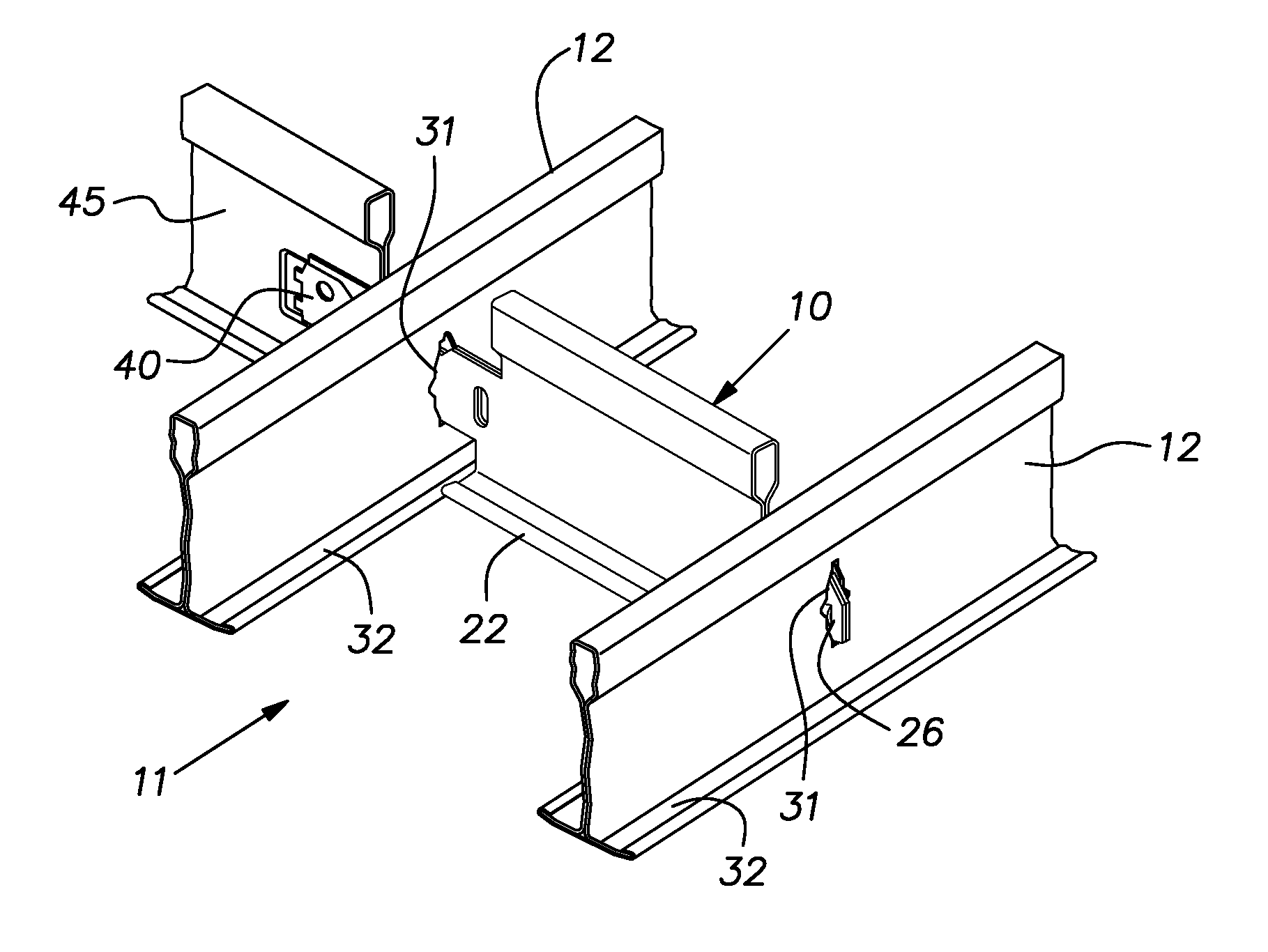
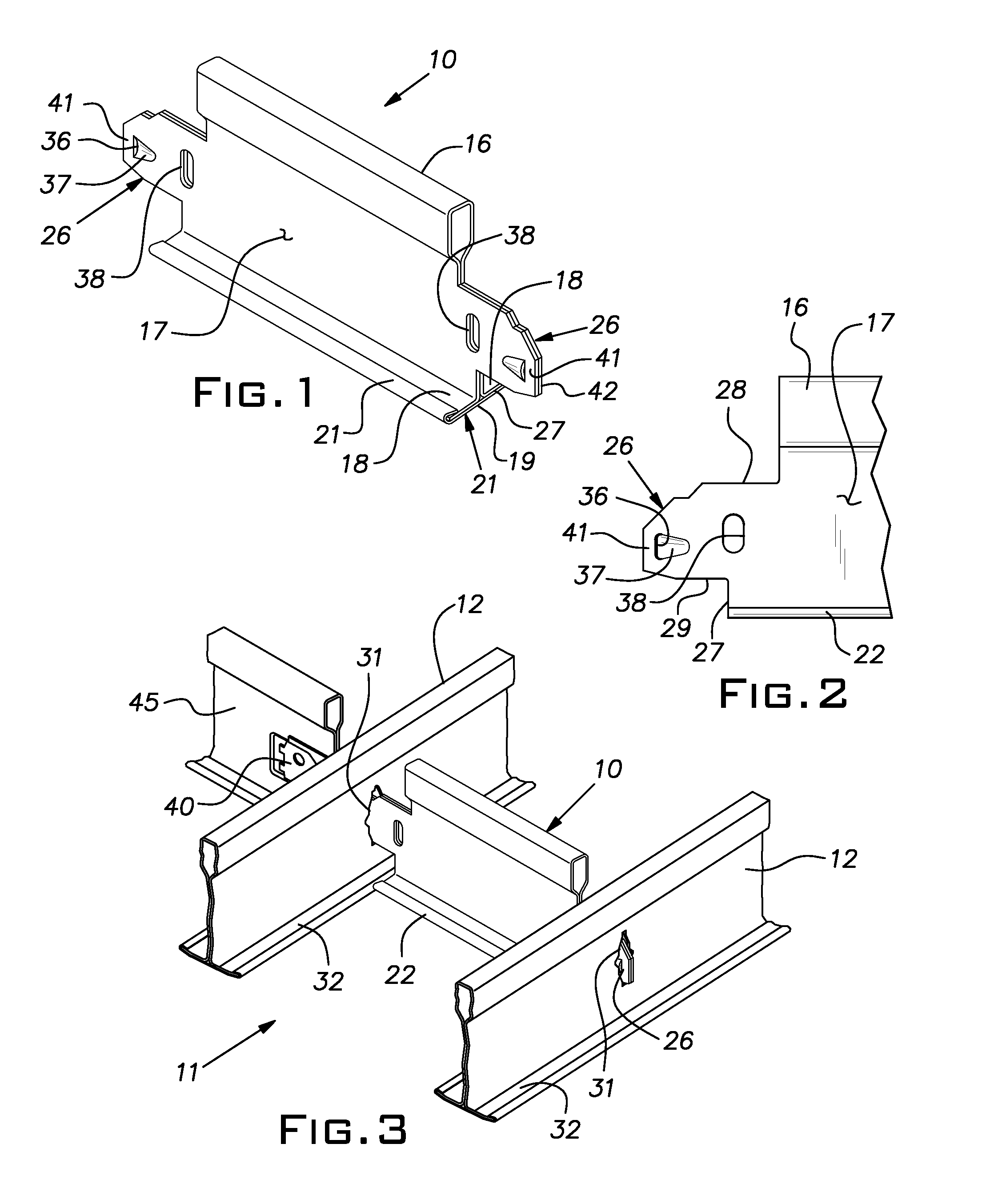
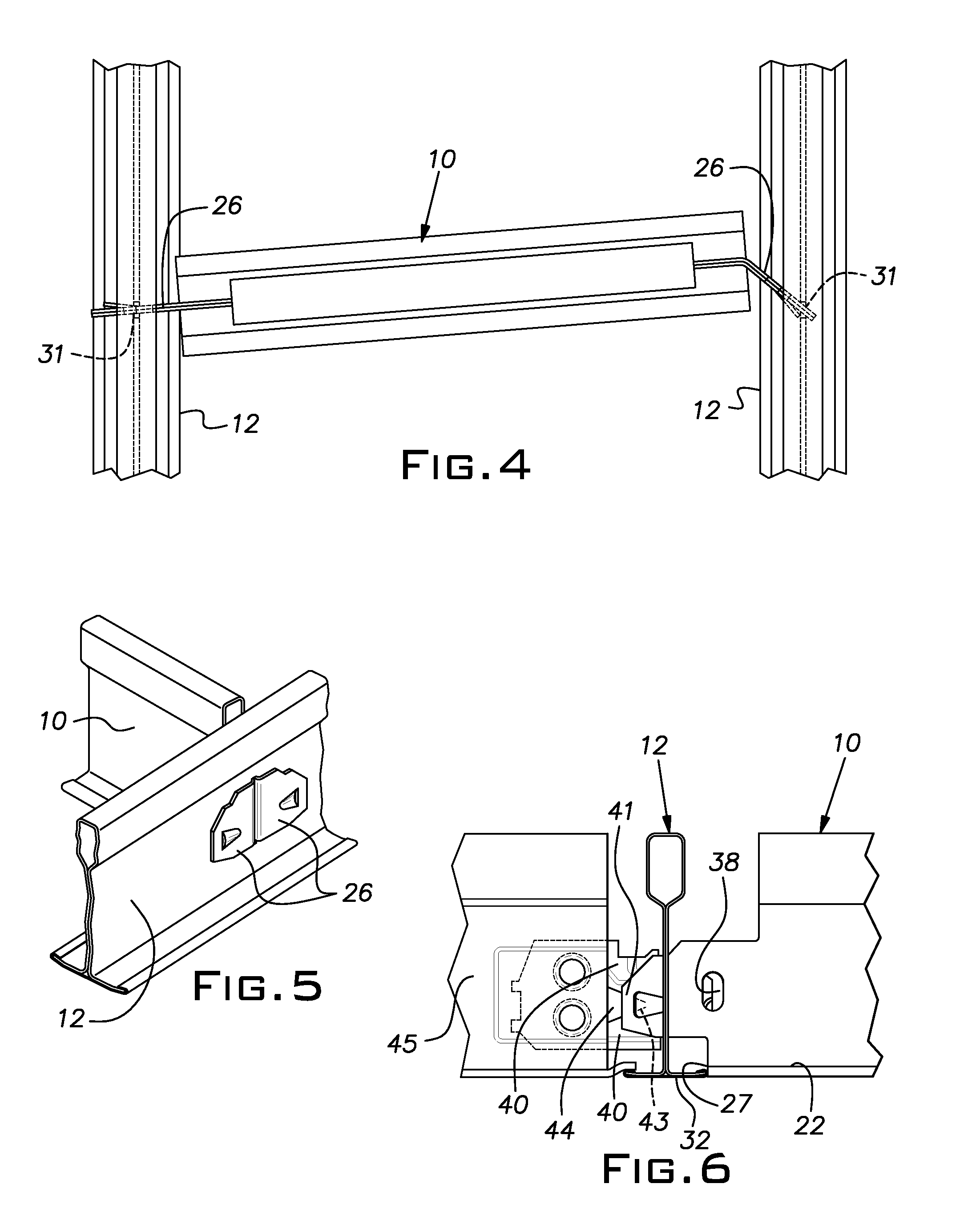
[0016]FIG. 1 illustrates a cross member 10 embodying the invention used in a narrow channel 11 depicted in FIG. 2. The channel 11 is employed as a part of a suspended ceiling grid to support utilities. The channel 11 is typically used with identical channels in spaced parallel lines across a ceiling. The channel 11 affords a popular ceiling treatment because it deploys utility hardware in a package that is less obtrusive than hardware that occupies a full grid module, which ordinarily is 2 foot by 2 foot or 2 foot by 4 foot (or industry metric equivalents thereof).

[0017]The channel 11 is formed by a pair of closely spaced parallel main runners or tees 12 of conventional construction used in a suspended ceiling grid. A center-to-center spacing of 4 inches or 6 inches (with metric equivalents of 100 mm. and 150 mm.) of the channel forming main tees 12 is standard in the industry. Channels 11 are normally arranged to extend transversely from wall-to-wall. Space inside the channel 11 is...


PUM


Abstract

A short cross member for a narrow utility channel formed of malleable sheet metal and having a vertical double ply web and a horizontal flange symmetrically disposed on both sides of a lower edge of the web, integral end connectors formed on each end of the cross member from sheet material contiguous with the web, the integral end connectors being arranged to support the flange in coplanar relation with flanges of the channel, the end connectors and the web being weakened at a predetermined vertical line whereby the cross member can be assembled in a narrow channel by bending at the associated line of weakness to shorten the effective overall length of the cross member.

Description

BACKGROUND OF THE INVENTION[0001]The invention relates to suspended ceiling construction and, in particular, to grid elements used with narrow utility channel systems.PRIOR ART[0002]Narrow channel systems are available for housing or otherwise locating various utility hardware in a conventional rectangular ceiling grid and tile construction. The channels are viewed as more harmonious or attractive than conventional arrangements for locating lights, air diffusers and returns, sprinklers and the like. Conventional arrangements, for example, dedicate a full grid module space to a single utility and, consequently, are more visually prominent than what is needed to ordinarily house a particular utility. The subject narrow channel systems, besides reducing the visibility of necessary utilities, can add to the attractiveness of a ceiling.[0003]It is known to construct narrow utility channels by aligning a pair of conventional main runners or tees in close parallel relation. A number of inv...

Claims


Application Information

Patent Timeline
Patent Type & Authority Patents(United States)
IPC IPC(8): E04C2/52E04B9/12E04B9/14
CPCE04B9/122E04B9/14E04B9/068E04B9/18
Inventor LEHANE, JR., JAMES J.GULBRANDSEN, PEDER J.PAULSEN, MARK R.UNDERKOFLER, ABRAHAM M.
Owner USG INTERIORS INC
Why Eureka
Try Eureka