Subgrate drain basin filter

a filter and sub-grate technology, applied in the direction of sewage draining, separation process, ways, etc., can solve the problems of heavy weight, unnecessarily high cost, and ineffective separation of sand or small particles by the apparatus

Inactive Publication Date: 2003-05-29
PAGE ARDLE E
View PDF0 Cites 20 Cited by
  • Summary
  • Abstract
  • Description
  • Claims
  • Application Information

AI Technical Summary

Problems solved by technology

Most of these inventions are unnecessarily expensive.
This apparatus is ineffective in separating sand or small particulate such as cigarette filters from the storm water before flowing downstream from the opening.
It is heavy and very complex.
This would be very expensive to manufacture.
They both require large equipment to install, and maintain.
This would be very time consuming and awkward to install, A grate is already heavy and hard to handle.
The frame when attached to the grate would be difficult to install without damaging the metal frame.
Furthermore its complexity makes it expensive to manufacture.
The device is unnecessarily complex.
The second stage basket cannot be serviced or emptied by hand unless the whole frame is removed.
The ridged frame cannot be easily adapted to the various sizes of grates and their angular distortions at typical installation sites.
The frame with its descending circumference is unnecessarily complex and expensive to manufacture.
This can be a traffic hazard.
They are exposed to wear and vandalism.
The receptacle however is limited in pollutant storage capacity.
There are four separate baskets, one on each comer, which makes it, time consuming to servi

Method used


Image

  • Subgrate drain basin filter
  • Subgrate drain basin filter
  • Subgrate drain basin filter

Examples


Embodiment Construction

. I-III

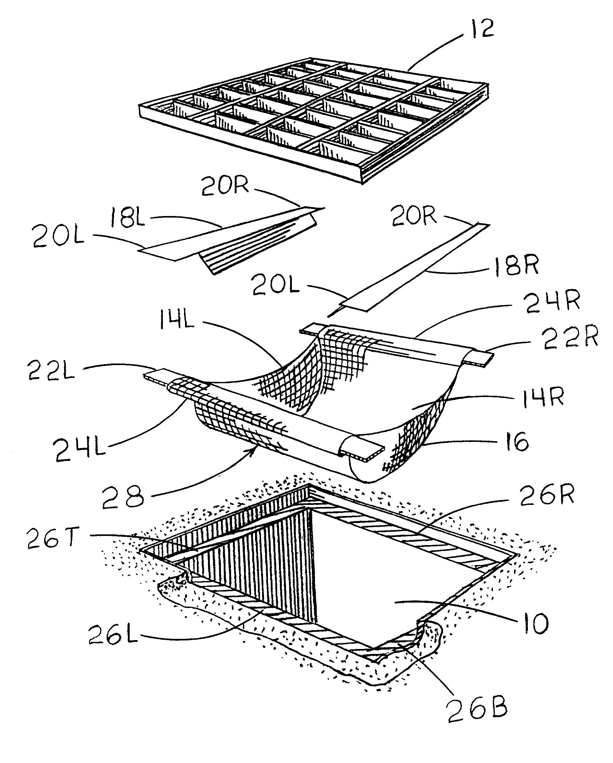
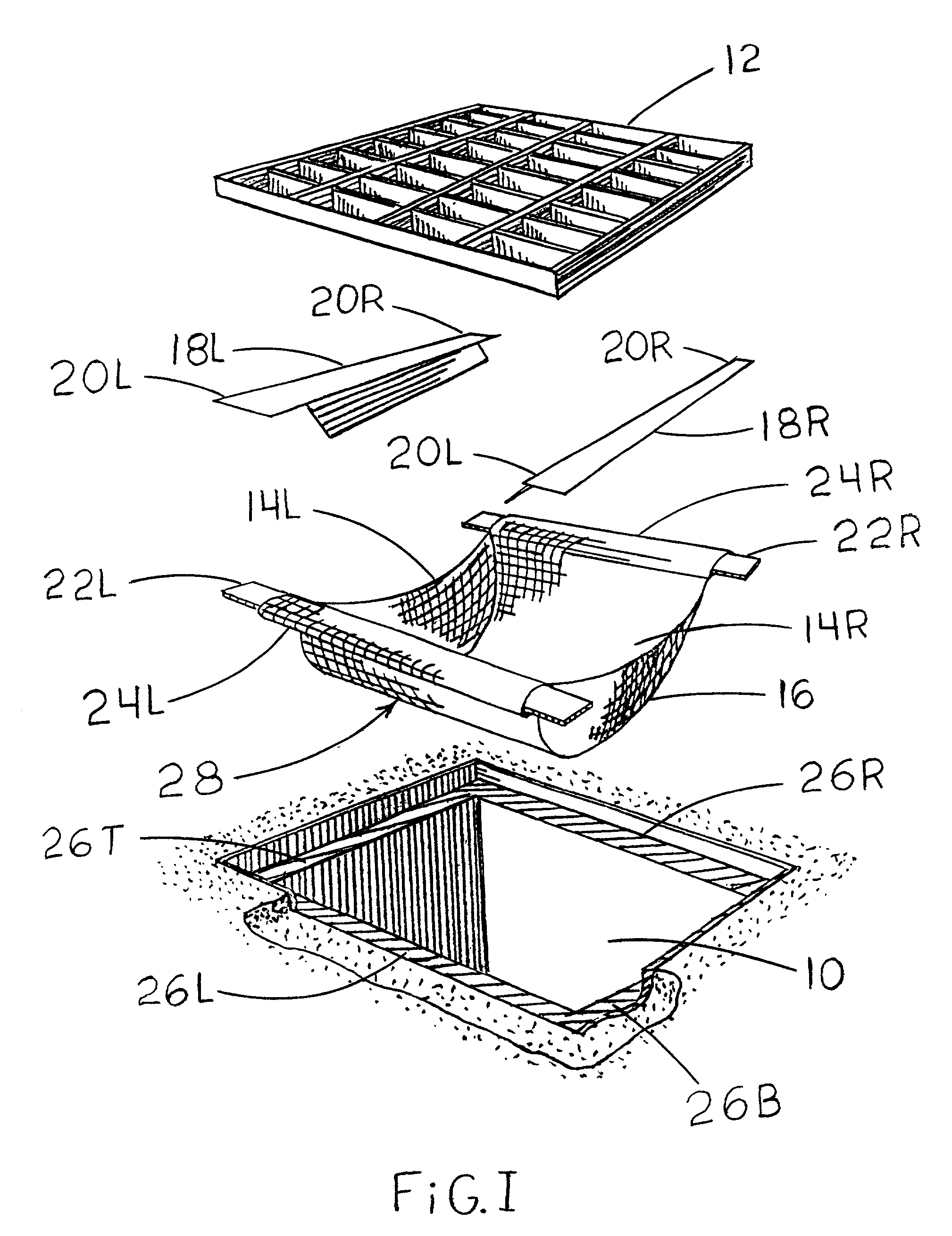
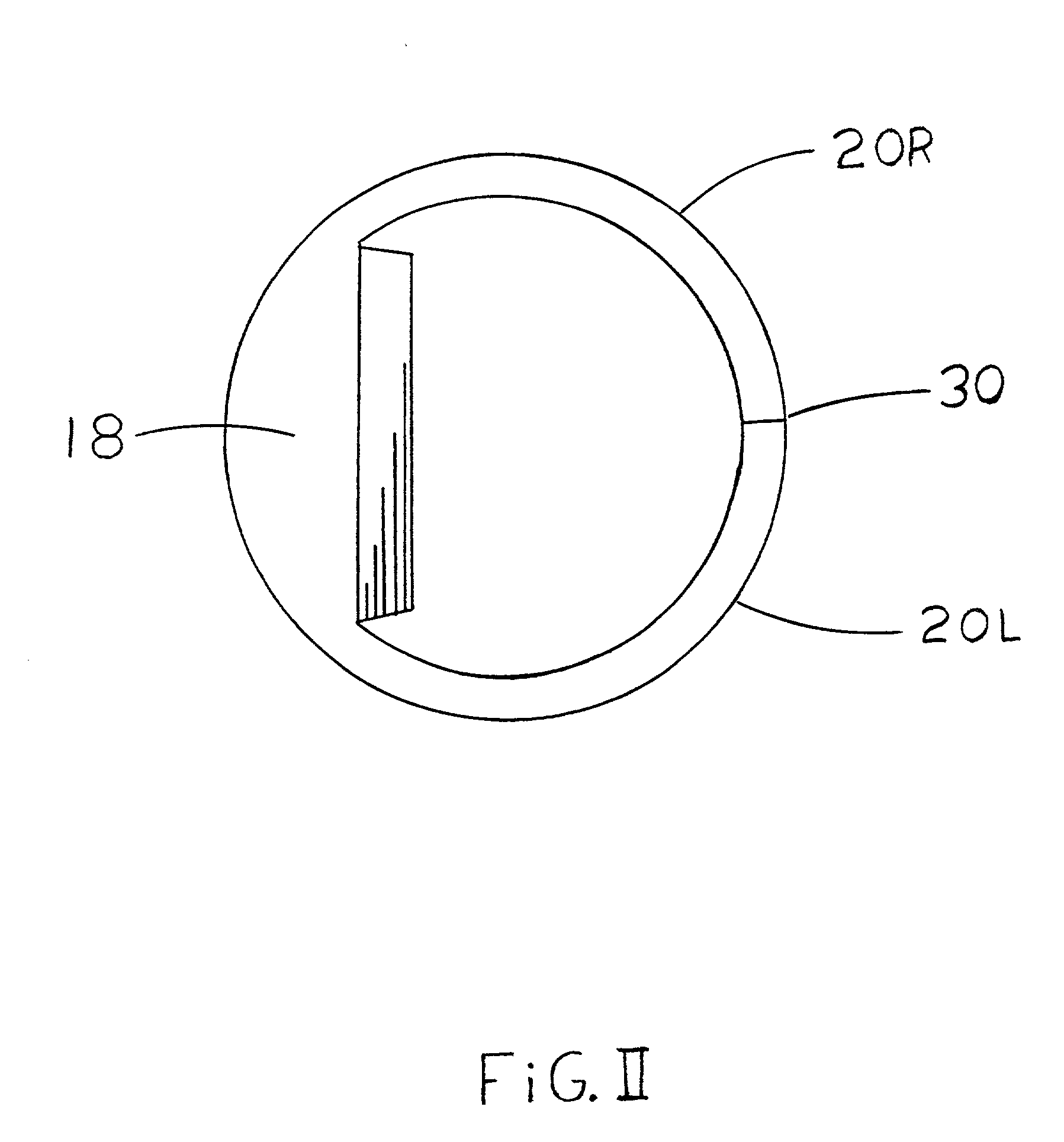
[0036] FIG. I best shows an exploded perspective of the invention in relation to its installed position in a typical rectangle inlet basin with a perforated cover. FIG. II shows the ridged support structure of the invention for a round inlet basin. FIG. III shows an exploded perspective view of the invention and installation arrangement in a round inlet basin beneath a perforated cover.

[0037] A bag assembly 28 comprises a filter basket 16 and two bar sleeves, 24L and 24R. The two bar sleeves enclose the two support bars 22L and 22R. The filter basket is made of a porous material with hydraulic openings smaller than the pollutants intended to be filtered from the storm water. The bag assembly is preferably made from a polypropylene geotextile fabric. However this filter may be made of many types of porous materials for example, cotton, burlap, or stainless, fiberglass, and aluminum mesh. The filter basket is connected to the support structure by means of sleeves.

[0038] The sup...


PUM

PropertyMeasurementUnit
Pressureaaaaaaaaaa
Electrical resistanceaaaaaaaaaa
Permeabilityaaaaaaaaaa

Abstract

The invention is a filter mounted below a perforated basin cover (12) of a storm water inlet basin (10) suspended from two ridged support bars (22) which rest upon a cover support (26) which are connected to a bag assembly (28) by inserting the support bars (22) into two bar sleeves (24) on a periphery of a filter basket (16) with a storm water bypass comprising a loop (14) and a bridge (18) which channels water above and over the loop into the inside of a filter basket (16).

Description

REFERENCES CITED[0001] U.S. Patent Documents1 U.S. Pat. Documents 1,746,121 February 1930 Adolph Levi 2,102,310 December 1937 George F. Egan 2,615,526 October 1952 F. Lane 4,419,232 December 1983 Oscar S. Arntyr et al. 5,575,925 November 1996 Logue, Jr. 6,045,691 April 2000 Holly S. McDermott[0002] U.S. patent application Ser. No. #09 / 769,212 Grp Art unit 1724 John F. Harris and Ardle E. PageBACKGROUND FIELD OF INVENTION[0003] This invention relates to a filter for use inside storm water inlet basins, beneath perforated covers such as perforated manhole receptacles and catch basins with grates.BACKGROUND-DESCRIPTION OF PRIOR ART[0004] Storm water collection systems are located throughout our city streets and parking lots providing flood control and drainage. The storm water needs to be as free as possible from pollutants before it enters our natural water systems such as streams. To ensure that our water sources are protected our handling of storm water is becoming more regulated. I...

Claims


Application Information

Patent Timeline
IPC IPC(8): E03F1/00
CPCE03F5/0404E03F1/00
Inventor PAGE, ARDLE E.
Owner PAGE ARDLE E
Why Eureka
Try Eureka