Supplemental mechanism for actuating the brake of a bicycle and methods of use

a technology for actuating the brake and bicycles, which is applied in the direction of bicycle brakes, cycle equipment, etc., can solve the problems of embolism and other problems, and achieve the effect of ensuring clipping

Inactive Publication Date: 2015-02-24
COOMBES ROGER WALTER
View PDF10 Cites 2 Cited by
  • Summary
  • Abstract
  • Description
  • Claims
  • Application Information

AI Technical Summary

Benefits of technology

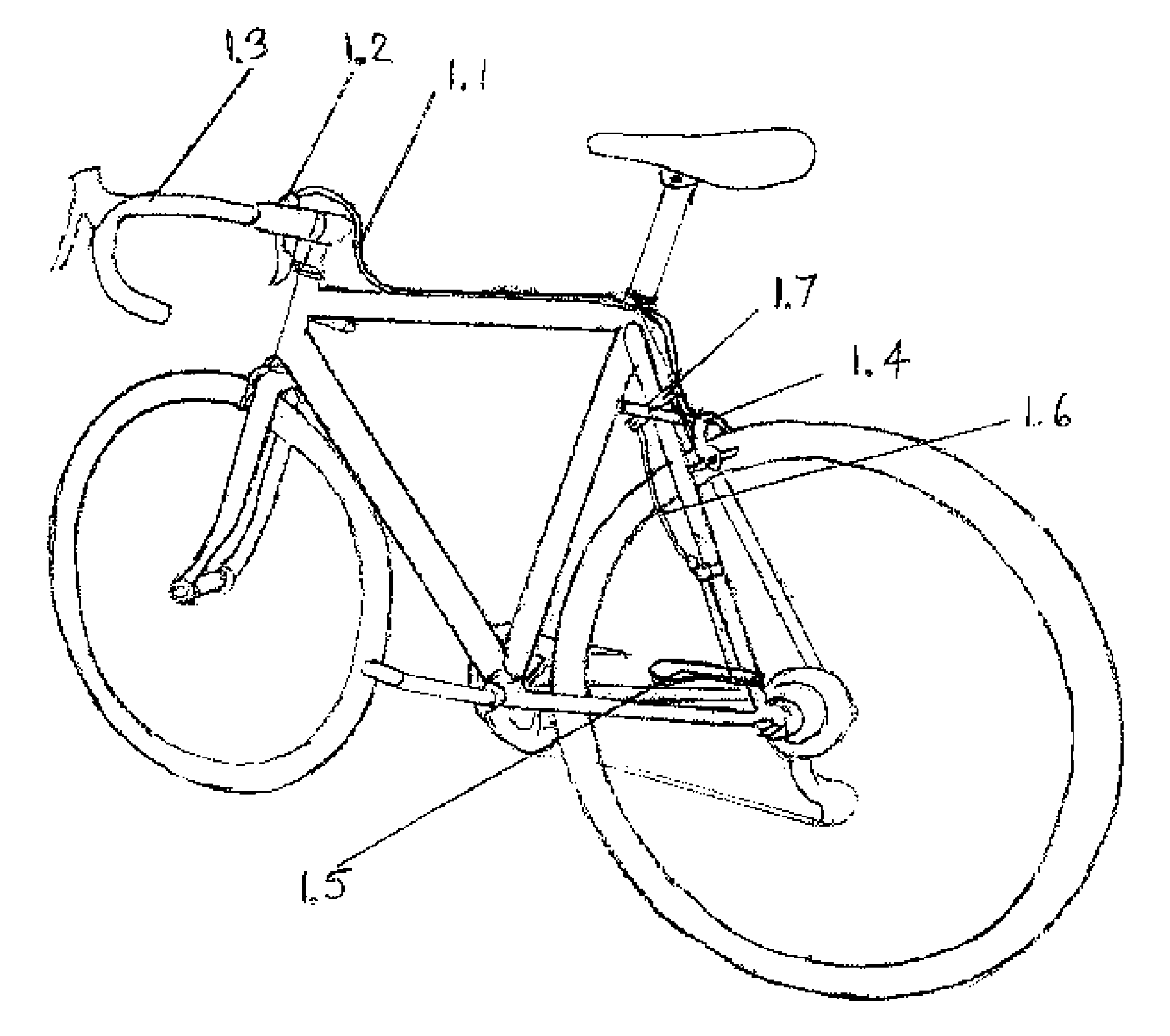
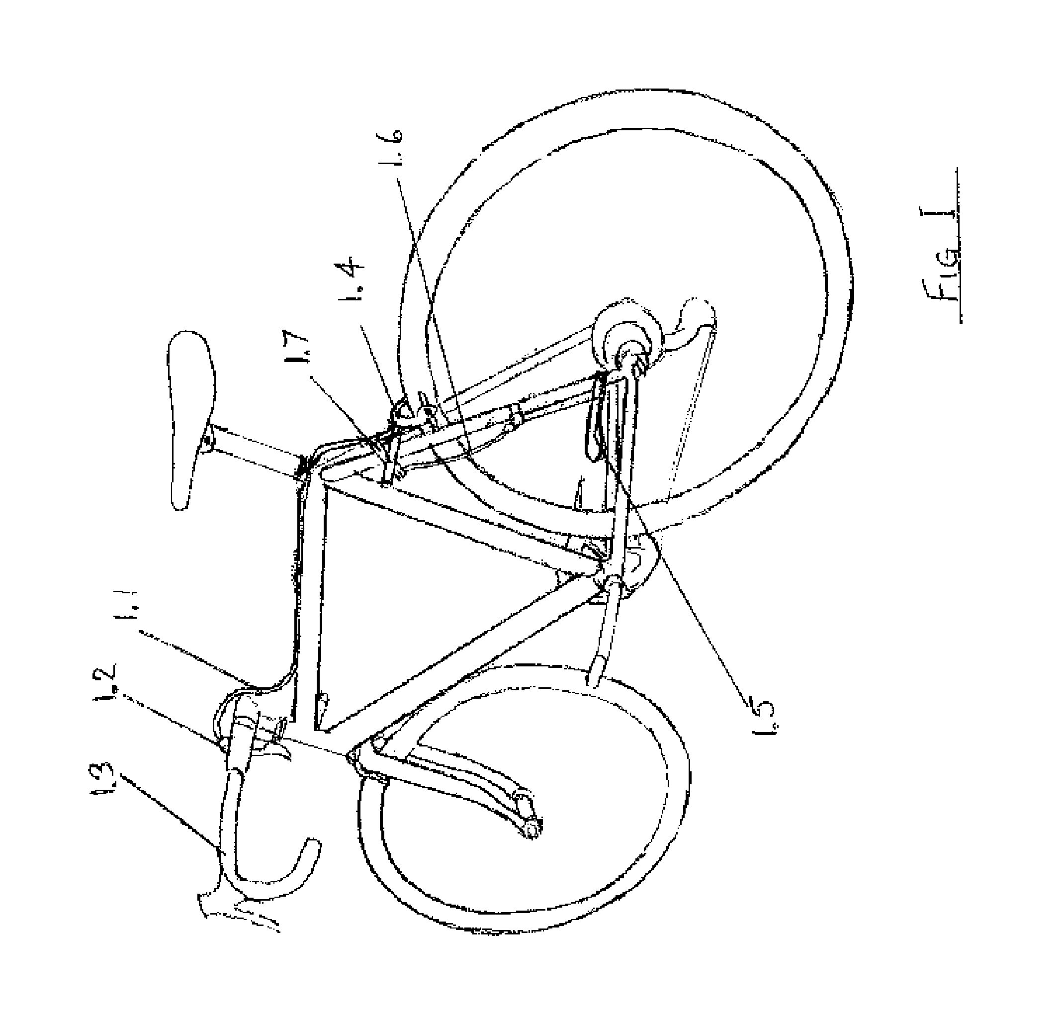
[0012]The distal end of the actuator is widened and is positioned such that during the upward stroke of normal pedaling, the shoe of the rider passes close to the side of the distal end of actuator but does not touch it. To operate the actuator, pedaling is stopped, the foot is rotated slightly inward on the pedal and the heel of the shoe is pressed down on the actuator. Most modern ‘clip-less’ pedals provide sufficient rotation of the foot to operate the actuator while the shoe is still engaged in the pedal. In the unusual case of zero rotation pedal clips it will be necessary to temporarily unclip the shoe from its retainer on the pedal but since the foot is only slightly rotated and not displaced it is always in position to be readily clipped in again. Applying pressure to the actuator can be accomplished by tipping the foot by rotating the ankle and generally it will not be necessary to rotate the pedals in the reverse direction.
[0016]Regardless of the brake system utilized, it is sometimes preferable to unequally distribute the brake force. In normal situations, the front brake handles the majority of the brake load and the weight bias is lifted from the rear tire. Thus, under these normal cycling circumstances, if equal pressures were applied to both front and back brakes, the rear wheel would end up skidding resulting in a loss of control. This invention allows for the independent adjustment of the front and rear brake lines or cables to keep the braking force consistent and maintain control.
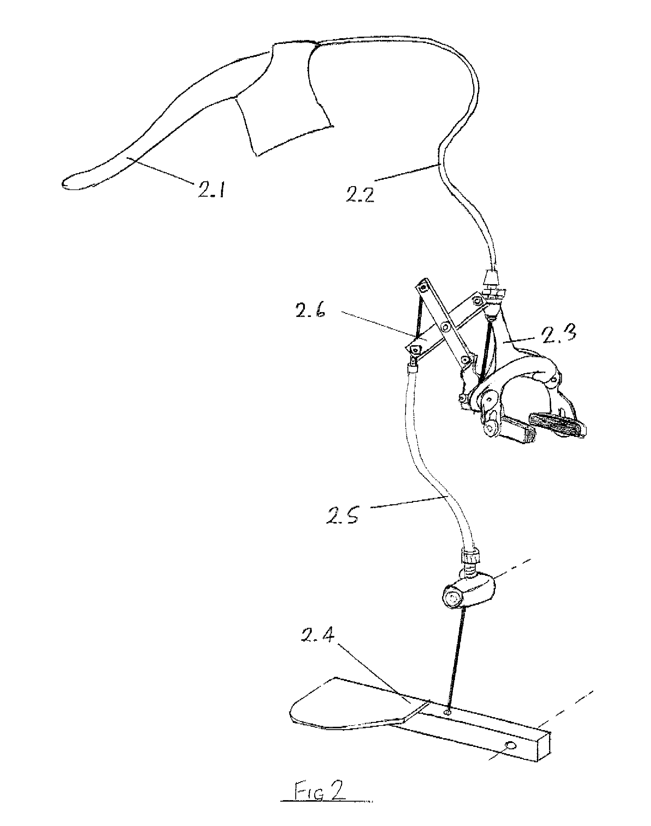
[0028]In a still further embodiment, a bicycle having a front wheel and a rear wheel is described. The bicycle includes a bicycle frame including a chain stay, a seat stay, a front brake, and a rear brake. The front brake is located on the rim of the front wheel or at a disc on the front wheel hub and said rear brake is located on the rim of the rear wheel or at a disc on the rear wheel hub or within the hub itself. The bicycle also includes a first pivot point mounted on said seat stay. The first pivot point is adjacent to the intersection of the chain stay and the seat stay such that the first pivot point is substantially within a reachable distance of the user's heel. The bicycle also includes a supplemental foot actuator rotatably mounted at said first pivot point. The supplemental actuator has a distal end and said distal end is widened such that the user of the bicycle can press said distal end downward. The bicycle also includes a foot lever hydraulic cylinder, electric control actuator or cable operatably connecting the supplemental foot actuator with the front bicycle brake and / or the rear brake such that both of the front brake and the rear brake reduce the speed of the bicycle when the supplemental foot actuator is actuated.

Problems solved by technology

Nor should such embodiments be construed to implement, or be limited to implementation of, any particular technical effect(s) or solution(s).

Method used


Image

  • Supplemental mechanism for actuating the brake of a bicycle and methods of use
  • Supplemental mechanism for actuating the brake of a bicycle and methods of use
  • Supplemental mechanism for actuating the brake of a bicycle and methods of use

Examples


Embodiment Construction

[0042]Detailed descriptions of embodiments of the invention are provided herein. It is to be understood, however, that the present invention may be embodied in various forms. Therefore, the specific details disclosed herein are not to be interpreted as limiting, but rather as a representative basis for teaching one skilled in the art how to employ the present invention in virtually any detailed system, structure, or manner.

[0043]Embodiments of the present invention would be of great value in any circumstance wherein a bicycle rider experiences difficulty controlling the speed of the bicycle by use of the hands alone. For example, at least one embodiment of the present invention would be of immediate benefit to cyclists who, because of disabilities do not have the full use of, or do not have sufficient strength in both hands to safely operate the normal hand operated brakes on a bicycle. For example, one-handed cyclists could operate one brake with their good hand and use the supplem...


PUM


Abstract

The present invention describes a supplemental mechanism for actuating the brake of a bicycle either independently or as an addition to normal hand operation of the brake by a brake lever on the handlebars. The actuating mechanism can be adapted to operate a variety of manufactured rim, disc or hub brakes and brake operating mechanisms, including but not limited to Bowden cables and hydraulic actuators and to a variety of different bicycle configurations including but not limited to tandems, (which here is used to describe any kind of multi-seat bicycle), recumbent bicycles and tricycles.

Description

CROSS-REFERENCE TO RELATED APPLICATIONS[0001]The present application claims the benefit of and priority to U.S. Provisional Patent Application Ser. No. 61 / 643,778, filed on May 7, 2012, the entirety of which is incorporated herein by reference.BACKGROUND OF THE DISCLOSURE[0002]1. The Field of the Invention[0003]The present application relates to the field of mechanisms for actuating the brake of a bicycle and methods of use. More particularly, the present invention relates to methods, machines, systems, sub-systems, assemblies, and components for providing supplemental mechanisms for actuating the brake of a bicycle and methods of use.[0004]2. The Relevant Technology[0005]Most bicycles today use hand brakes or a coaster brake. Most cyclists prefer bikes with hand brakes.[0006]As cyclists age or become injured, it may become difficult or impossible to actuate a front hand brake. For example, cyclists may have difficulty because of age, disease, or injury. Normal hand brake operation ...

Claims


Application Information

Patent Timeline
Patent Type & Authority Patents(United States)
IPC IPC(8): B62L3/02B62L3/04B62L1/16
CPCB62L3/04B62L1/16B62L3/02
Inventor COOMBES, ROGER WALTER
Owner COOMBES ROGER WALTER
Why Eureka
Try Eureka