Connector

a technology of connecting rods and connectors, applied in the direction of incorrect coupling prevention, coupling device connection, electrical apparatus, etc., can solve the problems of excessive stress, soldered parts may be cracked or finally broken, and the degree of freedom in design for the arrangement position of side retainers can be drastically widened, and prevent the action of excessive stress

Inactive Publication Date: 2015-03-10
SUMITOMO WIRING SYST LTD
View PDF11 Cites 20 Cited by
  • Summary
  • Abstract
  • Description
  • Claims
  • Application Information

AI Technical Summary

Benefits of technology

[0008]When the housing is fitted into the receptacle of the board connector with the holder mounted on the housing, the locking portion provided in the holder is engaged with the lower surface of the board. Thus, even if wires drawn out backward from the connector are pulled upwardly of the board, the locking portion is engaged with the board, thereby restricting the inclination of the housing and, further, the board connector and eventually preventing an excessive stress from acting on soldered parts of the metal fixtures.
[0009]Since the holder is formed separately from the housing and the lock member is provided only in the holder, it is sufficient to create only a manufacturing mold for the holder anew with a manufacturing mold for the housing kept as it is. Thus, this configuration can be inexpensively dealt with.
[0015]If the locking portion provided in the holder is structured to be integral with the housing, the arrangement position of a so-called side retainer is restricted to avoid interference when the side retainer is mounted into the housing. However, since the locking portion is provided in the holder separate from and mounted later on the housing, a degree of freedom in design for the arrangement position of the side retainer can be drastically widened.
[0016]According to the present invention, it is possible to prevent the action of an excessive stress on soldered parts of metal fixtures in a board connector.

Problems solved by technology

Since the wires are drawn out from the rear surface of the connector (female housing) in the board connector device as described above, the male housing of the board connector is pulled and, accordingly, an excessive stress may act on soldered parts of the metal fixtures and the soldered parts may be cracked or finally broken if, for example, the wires are pulled upward during wire laying or the like.

Method used


Image

  • Connector
  • Connector
  • Connector

Examples


Embodiment Construction

[0029]One embodiment of the present invention is described with reference to FIGS. 1 to 11.

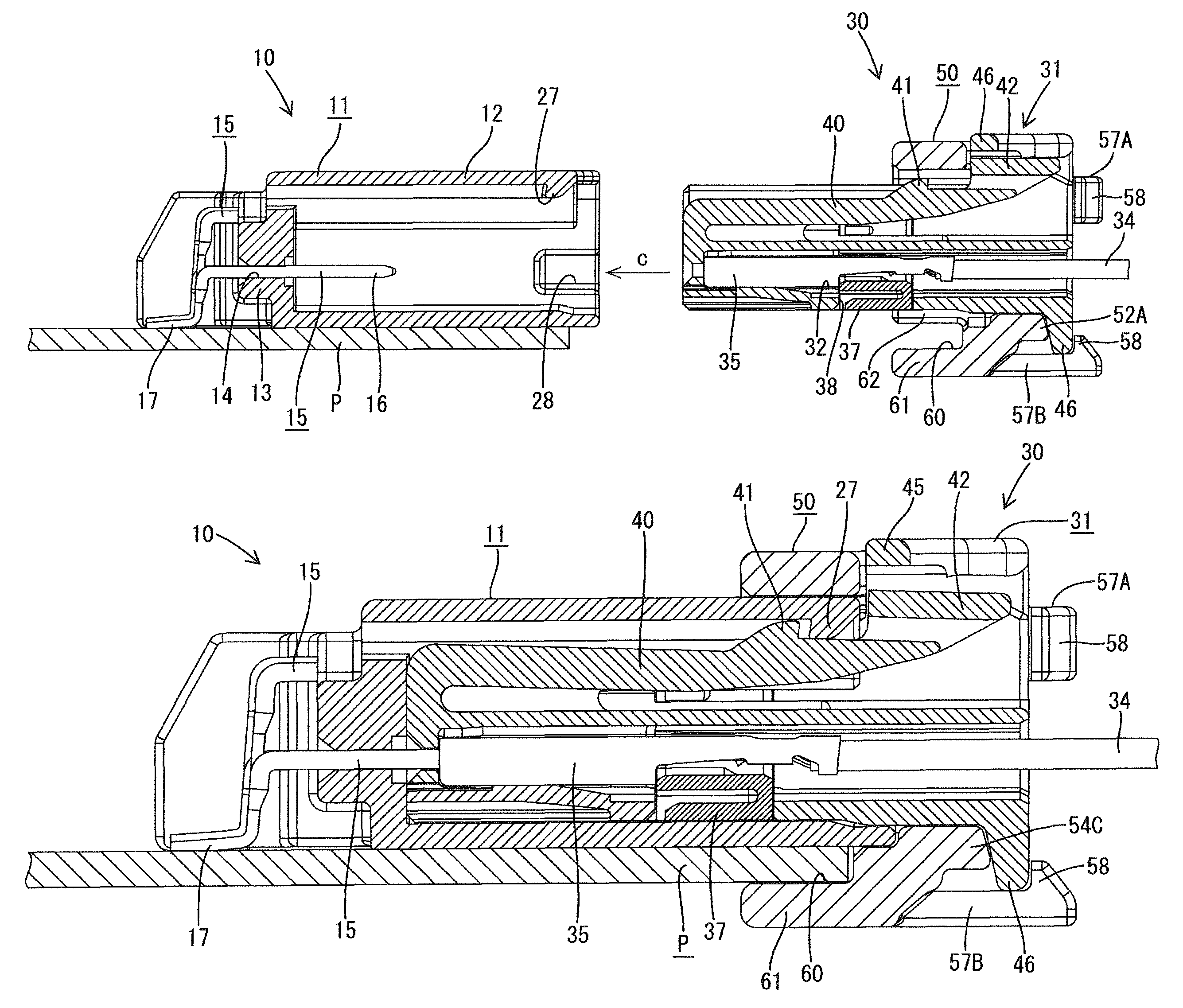
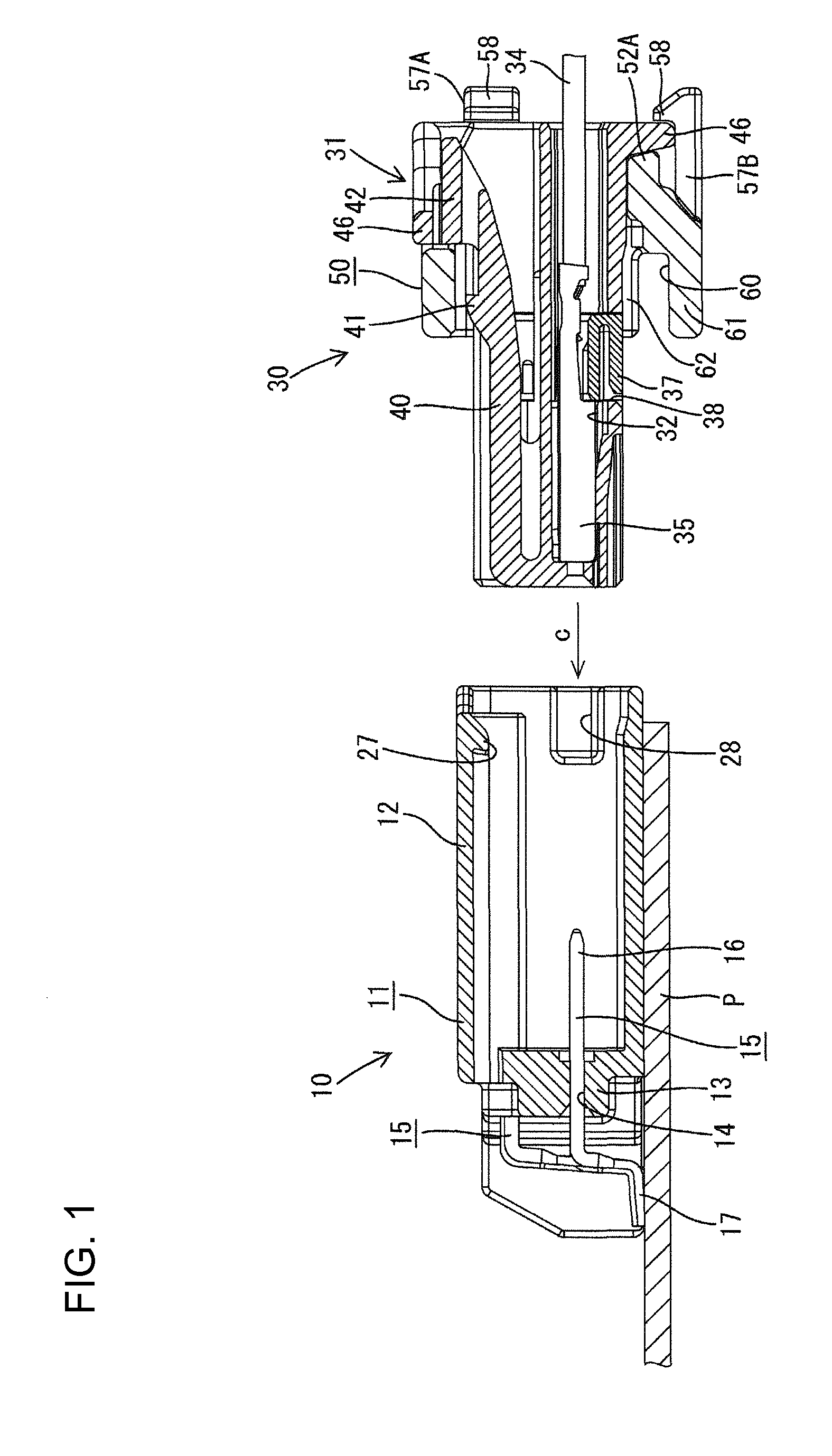
[0030]In this embodiment, as shown in FIG. 1, a harness-side connector 30 (corresponding to a connector of the present invention) connected to an end of a wiring harness is illustrated to be connected to a board connector 10 fixed to an end edge part of a printed wiring board P (hereinafter, merely referred to as a board P).

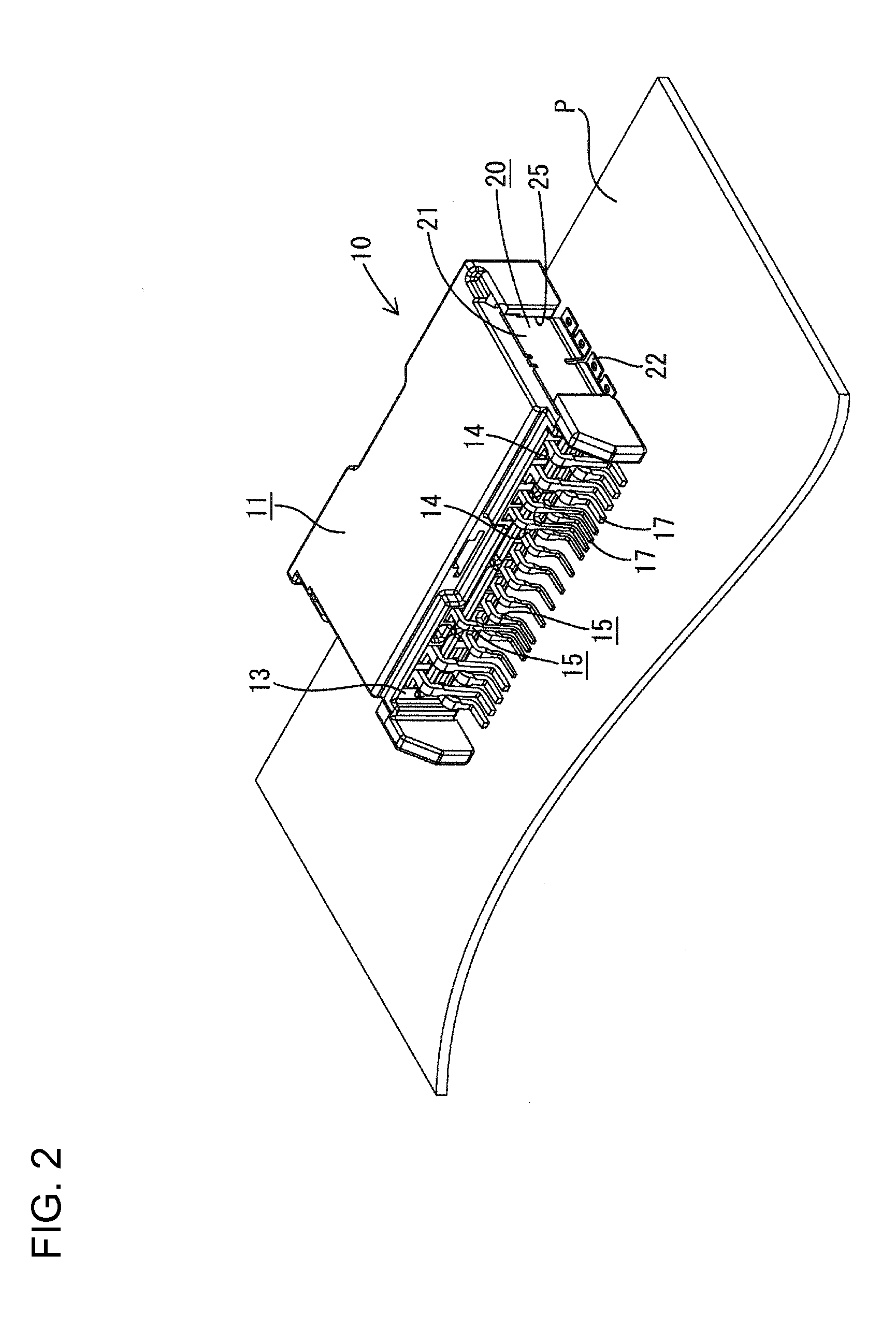
[0031]As shown in FIGS. 1 to 3, the board connector 10 includes a male housing 11 made of synthetic resin. This male housing 11 includes a receptacle 12 in the form of a flat rectangular tube with an open front surface, and a thick rear wall of this receptacle 12 serves as a terminal holding portion 13.

[0032]A plurality of terminal fittings 15 are mounted through the terminal holding portion 13 while being arranged in a lateral direction in two upper and lower levels. The terminal fittings 15 are formed by bending tabs into a crank shape and there are two types of larger an...


PUM


Abstract

A harness-side connector (30) to be connected to a board connector (10) whose metal fixtures (20) are fixed to the upper surface of a board (P) by soldering include a female housing (31) connected to an end of a wiring harness and fittable into a receptacle (12) of the board connector (10) and a holder (50) formed separately from the female housing (31). The holder (50) includes lock arms (57A, 57B) which are resiliently engaged with the female housing (31) to lock the holder (5) in a state mounted on the female housing (31) and a locking portion (61) which is engaged with the lower surface of the board (P) when the female housing (31) is fitted into the receptacle (12) of the board connector (10) after the holder (50) is mounted on the female housing (31).

Description

BACKGROUND OF THE INVENTION[0001]1. Field of the Invention[0002]The present invention relates to a connector to be connected to a board connector fixed to the upper surface of a board by soldering.[0003]2. Description of the Related Art[0004]A board connector device disclosed Japanese Unexamined Patent Publication No. 2007-87903 is known as an example of a board connector device of this type. The board connector includes a male housing including a receptacle with an open front surface and is structured such that tab-shaped terminal fittings are accommodated in this male housing while one ends are soldered to conductive paths of a board and the other ends are located in the receptacle and metal fixtures are mounted on both left and right side surfaces of the male housing. The board connector is fixed to the upper surface of an end edge part of the board by soldering the both metal fixtures. On the other hand, a connector to be connected to the board connector is connected to an end o...

Claims


Application Information

Patent Timeline
Patent Type & Authority Patents(United States)
IPC IPC(8): H01R13/64H01R12/72H01R13/516H01R13/627H01R13/639H01R107/00
CPCH01R13/639H01R12/724H01R12/721H01R2107/00H01R13/516H01R13/6272
Inventor AIHARA, TETSUYA
Owner SUMITOMO WIRING SYST LTD
Why Eureka
Try Eureka