Cable sealing device

a sealing device and cable technology, applied in the direction of insulating body, casing/cabinet/drawer details, electric apparatus, etc., can solve the problems of increased handling risks, high volatility, and increased risk of electronics of the fuel dispensing unit, so as to simplify the mounting of the same and reduce the amount of parts

Active Publication Date: 2015-03-17
DOVER FUELING SOLUTIONS UK LTD
View PDF5 Cites 5 Cited by
  • Summary
  • Abstract
  • Description
  • Claims
  • Application Information

AI Technical Summary

Benefits of technology

[0009]According to an embodiment a cable sealing device for sealing a cable passing through a first and second surface is provided. The cable sealing device comprises a first sealing element extending in a first radial direction of the cable and configured to surround at least a portion of the cable and to seal an opening in the first surface, and a second sealing element extending in a second radial direction of the cable and configured to surround at least a portion of the cable and to seal an opening in the second surface. The extension of the first sealing element in the first radial direction is smaller than the extension of the second sealing element in the second radial direction. This is advantageous in that the cable sealing device is constituted by a small number of parts and the mounting of the same is simplified in relation to prior art. Since the extension of the first sealing element in the first radial direction is smaller than the extension of the second sealing element in the second radial direction, the cable sealing device may be provided on the cable before it is passed through the surfaces to be sealed. Thus, the cable is automatically sealed when the first and second sealing element reaches the first and second surface, thereby simplifying the mounting to a great extent. In view of the above, the costs for manufacturing and mounting of the cable sealing device are decreased.
[0010]The first sealing element and second sealing element may be integrally formed, which is advantageous in that is decreases the amount of parts even further.
[0012]The cable sealing device may be attached to the cable to be sealed, which is advantageous in that the cable can be manufactured and distributed already provided with the cable sealing device. The mounting of the cable and the cable sealing device is thus further facilitated.
[0013]The second sealing element may have a flange adapted to fit into a corresponding recess of the opening to be sealed for retaining the second sealing element at said opening, which is advantageous in that a tight sealing will be ensured. Also, this way the amount of parts of the cable sealing device is kept down since no further locking device for the second sealing device will be needed.
[0014]The cable sealing device may further comprise a locking device for locking the first sealing element in the opening to be sealed, which is advantageous in that a tight sealing will be ensured.
[0015]The first sealing element and said second sealing element each may comprise a gasket for tight sealing against the openings to be sealed, which is advantageous in that a tight sealing will be ensured.

Problems solved by technology

An inherent property of fuel, that increases the risks of its handling, is its high volatility.
The electronics of the fuel dispensing unit can provide an increased risk in that for instance sparks from electronic circuitry and / or heat radiated from the electronic wiring and circuitry could ignite the fuel vapors.
However, in order to make the fuel dispensing unit operational it is necessary to pull cables between the hydraulics compartment and the electronics compartment, thereby risk leading inflammable substance from the hydraulic compartment up and into the electronics compartment.
A problem with sealing devices for cables according to this technique and other prior art is the vast amount of parts involved as well as the mounting of the same.
This procedure is both troublesome and time consuming.

Method used


Image

  • Cable sealing device
  • Cable sealing device
  • Cable sealing device

Examples


Embodiment Construction

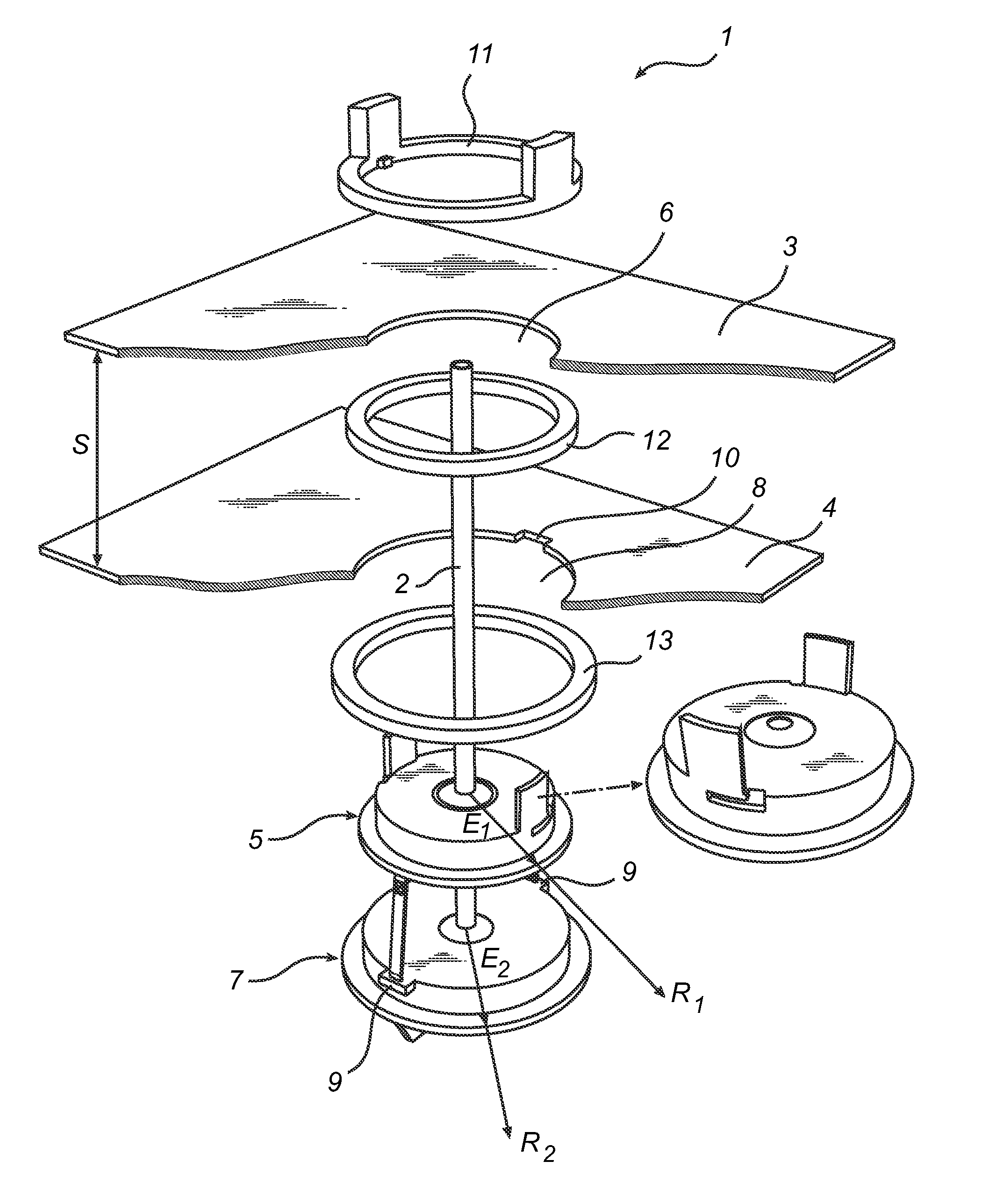
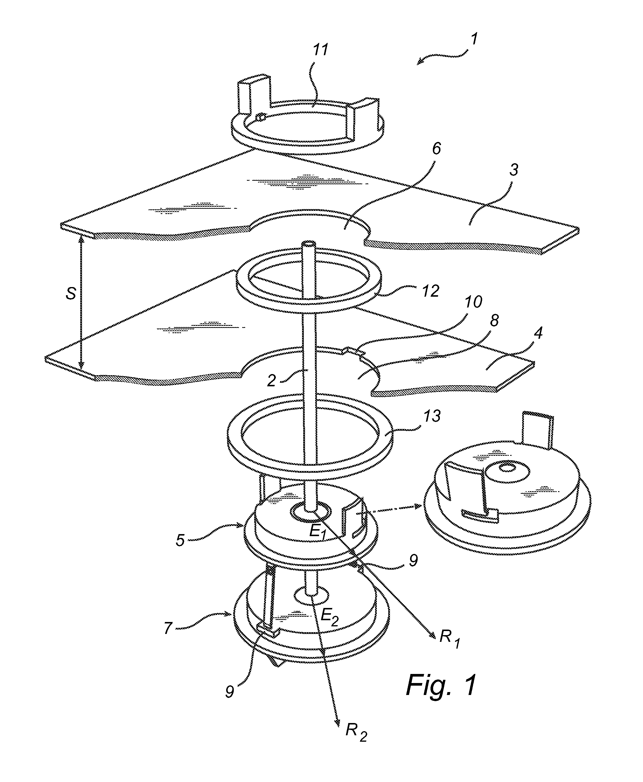
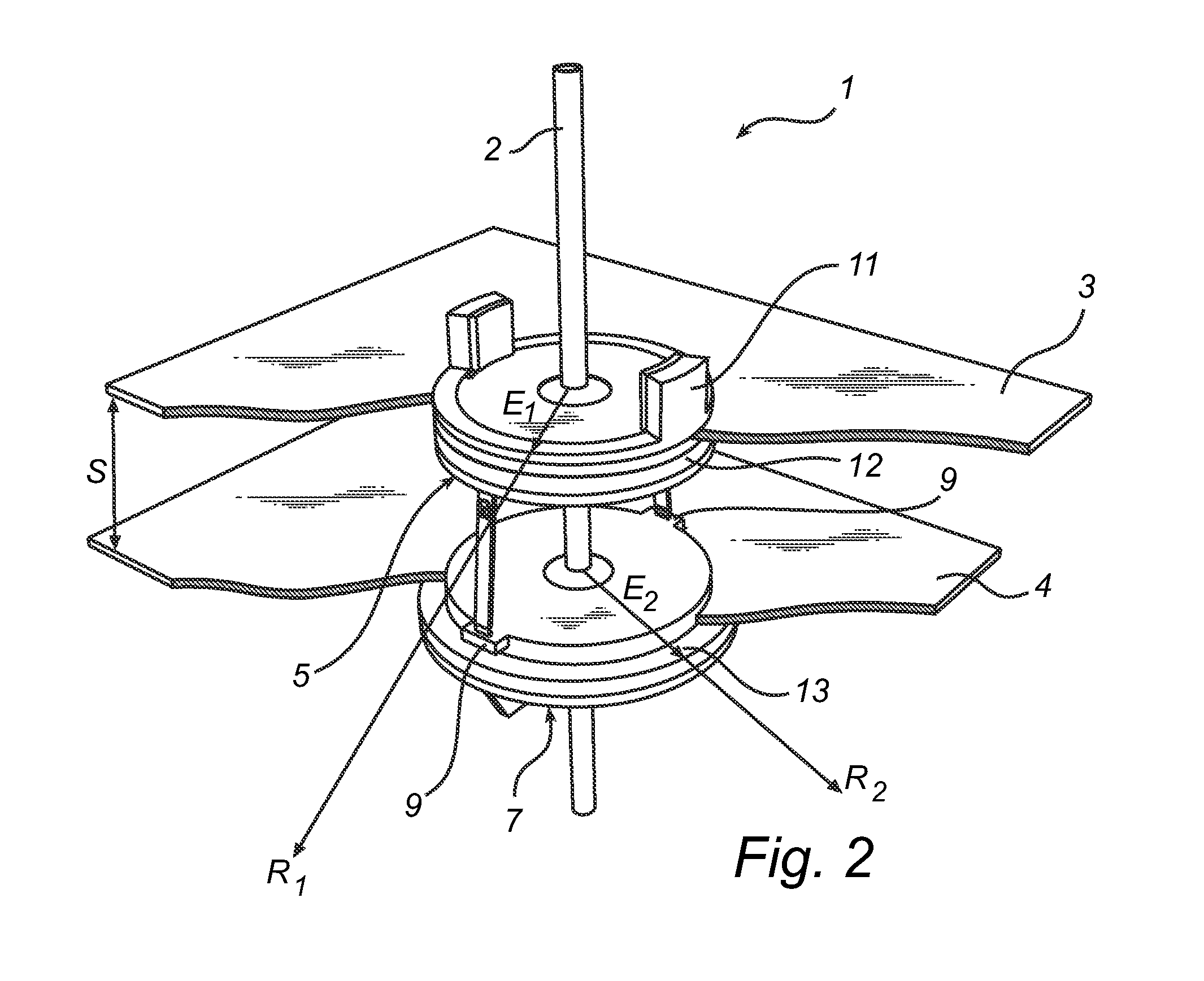
[0026]FIG. 1 illustrates a cable sealing device 1 according to one embodiment of the present invention when unassembled. The cable sealing device 1 is adapted to seal a cable 2 passing through a first surface 3 and a second surface 4, preferably in an electronics module of a fuel dispensing unit. The cable sealing device 1 has a first sealing element 5 extending in a first radial direction R1 of the cable 2 surrounding the cable 2, and is adapted to seal an opening 6 in the first surface 3. The cable sealing device 1 further has a second sealing element 7 extending in a second radial direction R2 of the cable 2 surrounding the cable 2, and is adapted to seal an opening 8 in the second surface 4. According to an alternative embodiment of the present invention the first 5 and second 7 sealing elements need not entirely surround the cable 2. That is, depending on specific sealing requirements the sealing elements 5, 7 may partially surround the cable so as to allow openings in the seal...


PUM


Abstract

A cable sealing device for sealing a cable passing through a first and second surface is provided. In one embodiment, the cable sealing device can include a first sealing element extending in a first radial direction of the cable and configured to surround at least a portion of the cable and to seal an opening in the first surface, and a second sealing element extending in a second radial direction of the cable and configured to surround at least a portion of the cable and to seal an opening in the second surface. The extension of the first sealing element in the first radial direction is smaller than the extension of the second sealing element in the second radial direction.

Description

CROSS REFERENCE TO RELATED APPLICATIONS[0001]This is a national stage application under 35 U.S.C. §371(c) of prior-filed, co-pending PCT patent application serial number PCT / EP2010 / 051308, filed on Feb. 3, 2010, the entire contents of which is incorporated herein by reference.BACKGROUND OF THE INVENTION[0002]Embodiments of the present invention relate to a cable sealing device for sealing a cable passing through a first and second surface.[0003]When passing a cable through a first and a second surface, the criteria of sealing that cable in relation to said two surfaces naturally differ depending of the environmental circumstances. If the surfaces are part of an arrangement handling an inflammable substance, such as a fuel dispensing unit, the criteria of the sealing is high.[0004]It is well-known that fuel, such as petrol or diesel, is a highly inflammable substance that must be handled with extreme care. An inherent property of fuel, that increases the risks of its handling, is its...

Claims


Application Information

Patent Timeline
Patent Type & Authority Patents(United States)
IPC IPC(8): H02G3/18B67D7/06H02G3/22H05K5/02
CPCB67D7/06H05K5/0247H02G3/22H01B17/265H01B17/301
Inventor LARSSON, BENGT I.JEPPSSON, NINACARLSSON, RICHARDLUNDGREN, CHRISTERFOLKELL, JONASTHEREN, PETTER
Owner DOVER FUELING SOLUTIONS UK LTD
Why Eureka
Try Eureka