Slide switch for use in electronic apparatus, and electronic apparatus

a technology of electronic equipment and slide switch, which is applied in the direction of cameras, instruments, camera body details, etc., can solve the problems of increasing the number of components and the installation space of the slide switch, reducing the accuracy of detecting the slide operation position of the slide lever, and poor contact between the armature parts, so as to enhance the accuracy of detecting the slide operation position

Inactive Publication Date: 2015-03-24
CANON KK
View PDF7 Cites 0 Cited by
  • Summary
  • Abstract
  • Description
  • Claims
  • Application Information

AI Technical Summary

Benefits of technology

[0010]The present invention provides a slide switch capable of enhancing the accuracy of detecting a slide operation position of a slide lever and the operability of the slide lever without increasing the number of components and an installation space for the slide switch, as well as an electronic apparatus having the slide switch.
[0013]According to the present invention, the accuracy of detecting a slide operation position of a slide lever and the operability of the slide lever can be enhanced without increasing the number of components and an installation space for the slide switch.

Problems solved by technology

However, according to Japanese Laid-Open Patent Publication (Kokai) No. 2005-267929 mentioned above, dirt produced in each of a plurality of armature portions may become attached to the adjacent armature portion and cause poor contact between the armature portions and signal patterns, which result in a decrease in the accuracy of detecting a slide operation position of the slide lever.
H05-034775 mentioned above, a switch unit constructed by combining a switch lever, a case, a soldering terminal, and so on into one unit is required, which leads to increases in the number of components and an installation space for the slide switch.
As a result, a user who is given a click feel when sliding the slide lever has a feeling of strangeness, and the operability of the slide lever deteriorates.

Method used


Image

  • Slide switch for use in electronic apparatus, and electronic apparatus
  • Slide switch for use in electronic apparatus, and electronic apparatus
  • Slide switch for use in electronic apparatus, and electronic apparatus

Examples


Embodiment Construction

[0026]A description will now be given of an exemplary embodiment of the present invention with reference to the drawings.

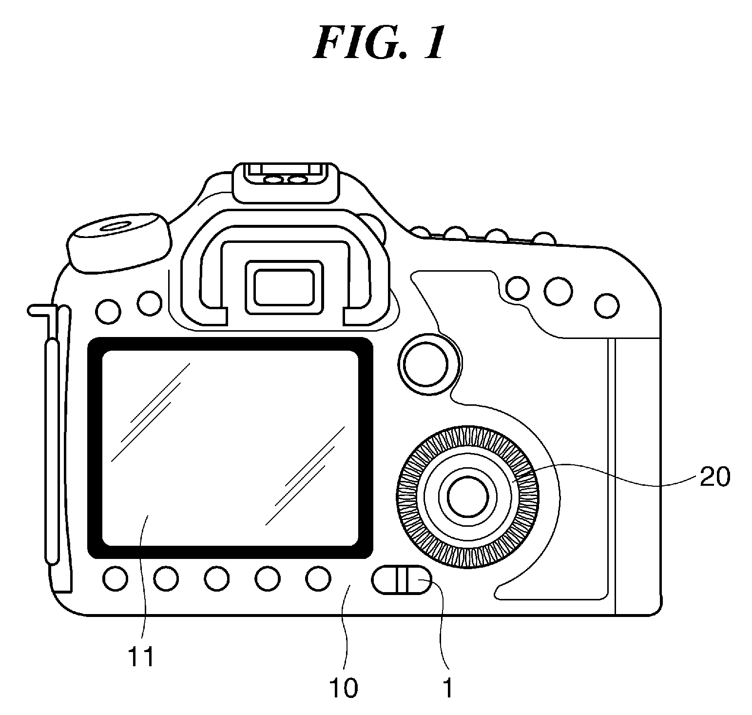
[0027]FIG. 1 is a rear view showing a digital camera having a slide switch, which is an exemplary embodiment of an electronic apparatus according to the present invention.

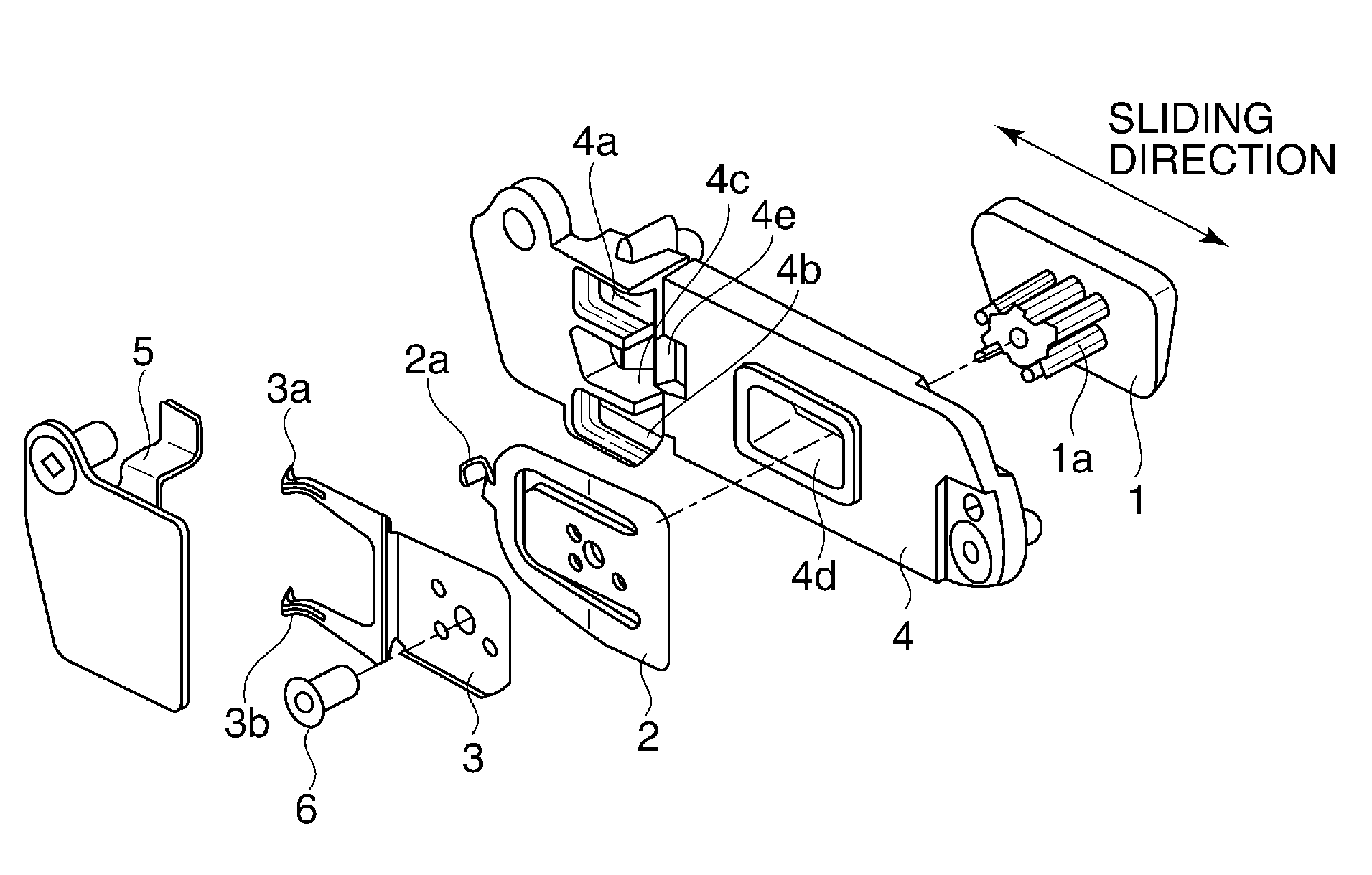
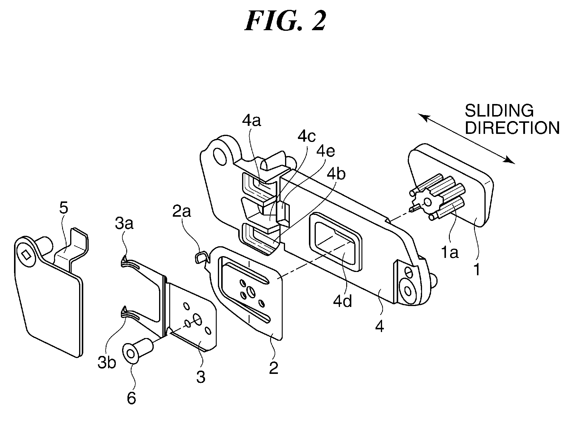
[0028]As shown in FIG. 1, an outer cover 10 on a rear side of the digital camera according to the present embodiment is equipped with a display 11 such as an LCD, an operation dial 20, and a slide lever 1 of the slide switch.

[0029]It should be noted that in the present embodiment, when the slide lever 1 is in a first operation position, to be described later, a controller of the digital camera accepts a command operation of the operation dial 20. When the slide lever 1 is in a second operation position, to be described later, the controller of the digital camera performs control so as not to accept a command operation of the operation dial 20.

[0030]Namely, the controller of the digital camera per...


PUM


Abstract

A slide switch capable of enhancing the accuracy of detecting a slide operation position of a slide lever and the operability of the slide lever without increasing the number of components and an installation space for the slide switch. An elastically-deformable click portion is disposed on a line passing through the center of a slide shaft of the slide lever and extending in a sliding direction in which the slide lever slides, moves integrally with the slide lever, and gets over a convex portion formed in a base member to generate a click force. In an accommodation space which accommodates the click portion and a plurality of armature portions, the click portion and one armature portion of the plurality of armature portions are separated from each other by a first partition, and the click portion and the other armature portion are separated from each other by a second partition.

Description

BACKGROUND OF THE INVENTION[0001]1. Field of the Invention[0002]The present invention relates to a slide switch for use in an electronic apparatus such as a digital camera, and an electronic apparatus having the slide switch.[0003]2. Description of the Related Art[0004]Examples of a slide switch for use in an electronic apparatus such as a digital camera include one having a slide lever, a click portion that gives a user a click feel when the slide lever is slid, and armature portions for detecting a slide operation position of the slide lever.[0005]For such a slide switch, there has been proposed a technique that prevents dirt or the like including lubricating oil produced in the click portion from becoming attached to the armature portions so as to prevent a slide operation position of the slide lever from being incorrectly detected (Japanese Laid-Open Patent Publication (Kokai) No. 2005-267929).[0006]There has also been proposed a technique that disposes the click portion paralle...

Claims


Application Information

Patent Timeline
Patent Type & Authority Patents(United States)
IPC IPC(8): H01H15/02G03B17/02G03B17/04G03B19/12H01H15/10
CPCG03B17/04H01H15/02H01H15/10G03B17/02G03B19/12G03B2217/002
Inventor KOIWAI, HIROSHI
Owner CANON KK
Why Eureka
Try Eureka