Vehicular cooling system

a cooling system and vehicle technology, applied in the direction of electrochemical generators, battery/fuel cell control arrangement, etc., can solve the problems of increasing the cost and weight of a vehicle, insufficient cooling effect of the battery, etc., to increase the temperature of the battery, increase the cooling effect, and improve the cooling

Active Publication Date: 2020-07-14
TOYOTA JIDOSHA KK
View PDF16 Cites 2 Cited by
  • Summary
  • Abstract
  • Description
  • Claims
  • Application Information

AI Technical Summary

Benefits of technology

[0004]When the configuration of the unit cooling circuit described in JP 2014-073802 A is employed, the coolant that has been cooled by the radiator is subjected to heat exchange with the battery after cooling the oil cooler. This makes the effect of cooling the battery insufficient. Thus, it is necessary to additionally provide a battery cooling circuit configured to cool the battery by using the outside air. Therefore, the number of components is increased, resulting in increases in cost and weight of a vehicle. As described in JP 2002-291106 A, when the temperature of the battery is low, it is necessary to increase the temperature of the battery in order to enhance the power efficiency. However, when the charged power is used to increase the temperature of the battery, the amount of charge is decreased.
[0005]The present disclosure provides a vehicular cooling system configured to cool a battery and increase the temperature of the battery without significantly increasing the number of components.
[0010]With the foregoing configuration, the coolant that has been cooled to a low temperature by the radiator can be supplied to the battery and the power control unit in parallel. Thus, it is possible to enhance the performance of cooling each of the battery and the power control unit. With the foregoing configuration, the coolant that has been cooled to a low temperature by the radiator can be preferentially supplied toward the transmission oil cooler, when a higher priority is given to cooling of the transmission oil than to cooling of the battery and the power control unit, for example, when a vehicle is traveling at a high speed in a steady state.
[0011]In the vehicular cooling system according to the aspect of the present disclosure, the same coolant is used both to cool the battery and to perform heat exchange in the transmission oil cooler. Thus, it is possible to cool the battery without significantly increasing the number of components. Further, when the temperature of the battery is low, it is possible to increase the temperature of the battery by using heat of the coolant that has been discharged from the transmission oil cooler.

Problems solved by technology

This makes the effect of cooling the battery insufficient.
Therefore, the number of components is increased, resulting in increases in cost and weight of a vehicle.

Method used


Image

  • Vehicular cooling system
  • Vehicular cooling system

Examples


first embodiment

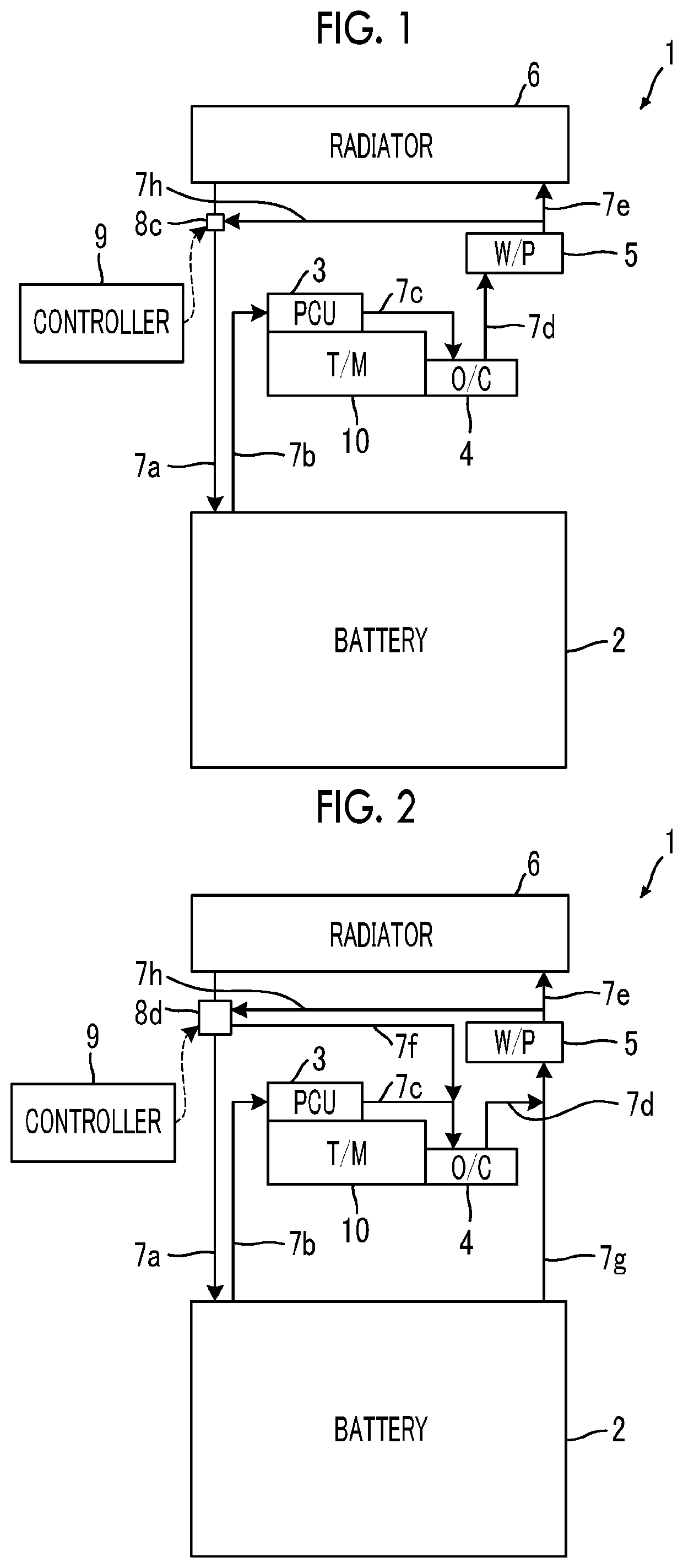
[0019]First, the configuration of a vehicular cooling system according to a first embodiment of the present disclosure will be described with reference to FIG. 1.

[0020]FIG. 1 is a schematic diagram illustrating the configuration of the vehicular cooling system according to the first embodiment of the present disclosure. A vehicular cooling system 1 according to the first embodiment of the present disclosure is mounted in a vehicle, such as an electric automobile, and the vehicular cooling system 1 includes a battery 2, a power control unit (hereinafter, referred to as “PCU”) 3, a transmission oil cooler (hereinafter, referred to as “oil cooler”, and abbreviated as “O / C” in the drawings) 4, a water pump (abbreviated as “W / P” in the drawings) 5, and a radiator 6 as main components, as illustrated in FIG. 1. The target cooling temperature for the battery 2, the target cooling temperature for the PCU 3, and the target cooling temperature for the oil cooler 4 ascend (i.e., rise) in this ...

second embodiment

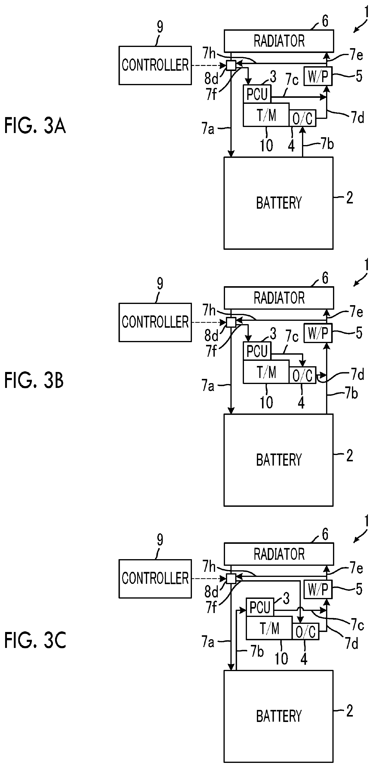
[0031]The configuration of a vehicular cooling system according to a second embodiment of the present disclosure will be described with reference to FIG. 2, FIG. 3A, FIG. 3B, and FIG. 3C. Hereinafter, only the configurations different from those of the vehicular cooling system 1 in FIG. 1 will be described, and description of the same configurations as those of the vehicular cooling system 1 in FIG. 1 will be omitted.

[0032]FIG. 2 is a schematic diagram illustrating the configuration of the vehicular cooling system according to the second embodiment of the present disclosure. As illustrated in FIG. 2, in the second embodiment, the battery 2 is provided with the coolant passage 7b and a coolant passage 7g. The coolant that has been subjected to heat exchange with the battery 2 is discharged to the water pump 5 through the coolant passage 7g. The outlet of the coolant passage 7d is connected to the coolant passage 7g. A flow-regulating and switching valve 8d is provided at a connection...


PUM


Abstract

A coolant passage of a vehicular cooling system includes a battery coolant passage through which a coolant is supplied from a radiator to a battery, a discharge coolant passage through which the coolant is supplied to the radiator, a first bypass passage through which the coolant is supplied from the discharge coolant passage to the battery coolant passage while bypassing the radiator, and a switching valve that switches a pathway of the coolant, between a first pathway through which the coolant is supplied from the discharge coolant passage to the battery coolant passage via the radiator and a second pathway through which the coolant is supplied from the discharge coolant passage to the battery coolant passage via the first bypass passage. An electronic control unit controls the switching valve such that the pathway is switched to the second pathway at the time of increasing a temperature of the battery.

Description

INCORPORATION BY REFERENCE[0001]The disclosure of Japanese Patent Application No. 2017-183136 filed on Sep. 25, 2017 including the specification, drawings and abstract is incorporated herein by reference in its entirety.BACKGROUND1. Technical Field[0002]The present disclosure relates to a vehicular cooling system.2. Description of Related Art[0003]Japanese Unexamined Patent Application Publication No. 2014-073802 (JP 2014-073802 A) describes a hybrid vehicle (HV) including a battery cooling circuit and a unit cooling circuit. The battery cooling circuit is configured to air-cool a battery. In the unit cooling circuit, a coolant stored in a reservoir tank is subjected to heat exchange with the air for cooling the battery, the coolant is then supplied to a radiator and cooled by the radiator, and then the coolant that has been subjected to heat exchange performed by an oil cooler is returned to the reservoir tank. Japanese Unexamined Patent Application Publication No. 2002-291106 (JP ...

Claims


Application Information

Patent Timeline
Patent Type & Authority Patents(United States)
IPC IPC(8): B60L58/26B60K11/02B60K1/00B60K11/04
CPCB60K1/00B60K11/02B60L58/26B60K11/04B60K2001/005B60L2240/36H01M10/613H01M10/615H01M10/625H01M10/63H01M10/6568H01M10/66H01M2220/20
Inventor TOMINAGA, SATOSHITOKOZAKURA, DAISUKESEKI, YUSHI
Owner TOYOTA JIDOSHA KK
Why Eureka
Try Eureka