

Hydraulic shock absorber
a technology of shock absorber and shock absorber, which is applied in the direction of shock absorbers, vibration dampers, springs/dampers, etc., can solve the problems of inability to obtain and inability to achieve a great change of damping force according to the stroke. achieve the effect of stably increasing the damping for
- Summary
- Abstract
- Description
- Claims
- Application Information
AI Technical Summary
Benefits of technology
Problems solved by technology
Method used
Image

Examples
first embodiment
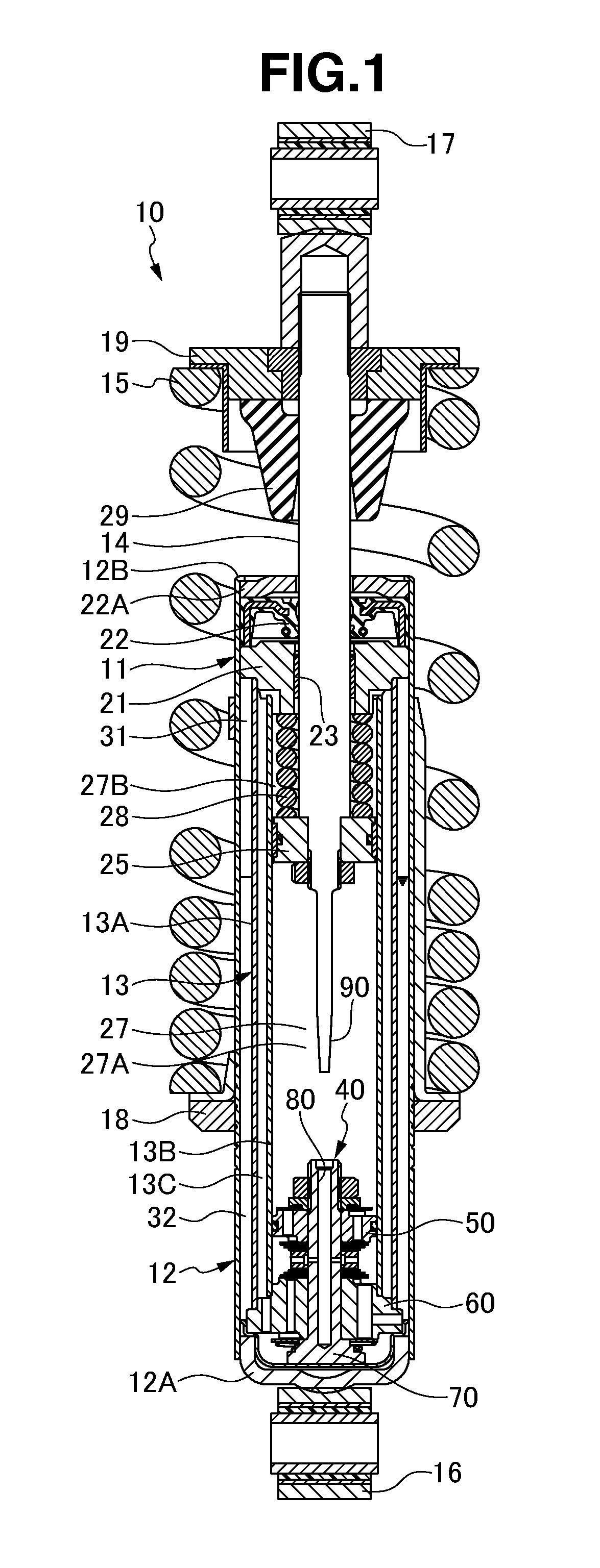
FIGS. 1 to 5C
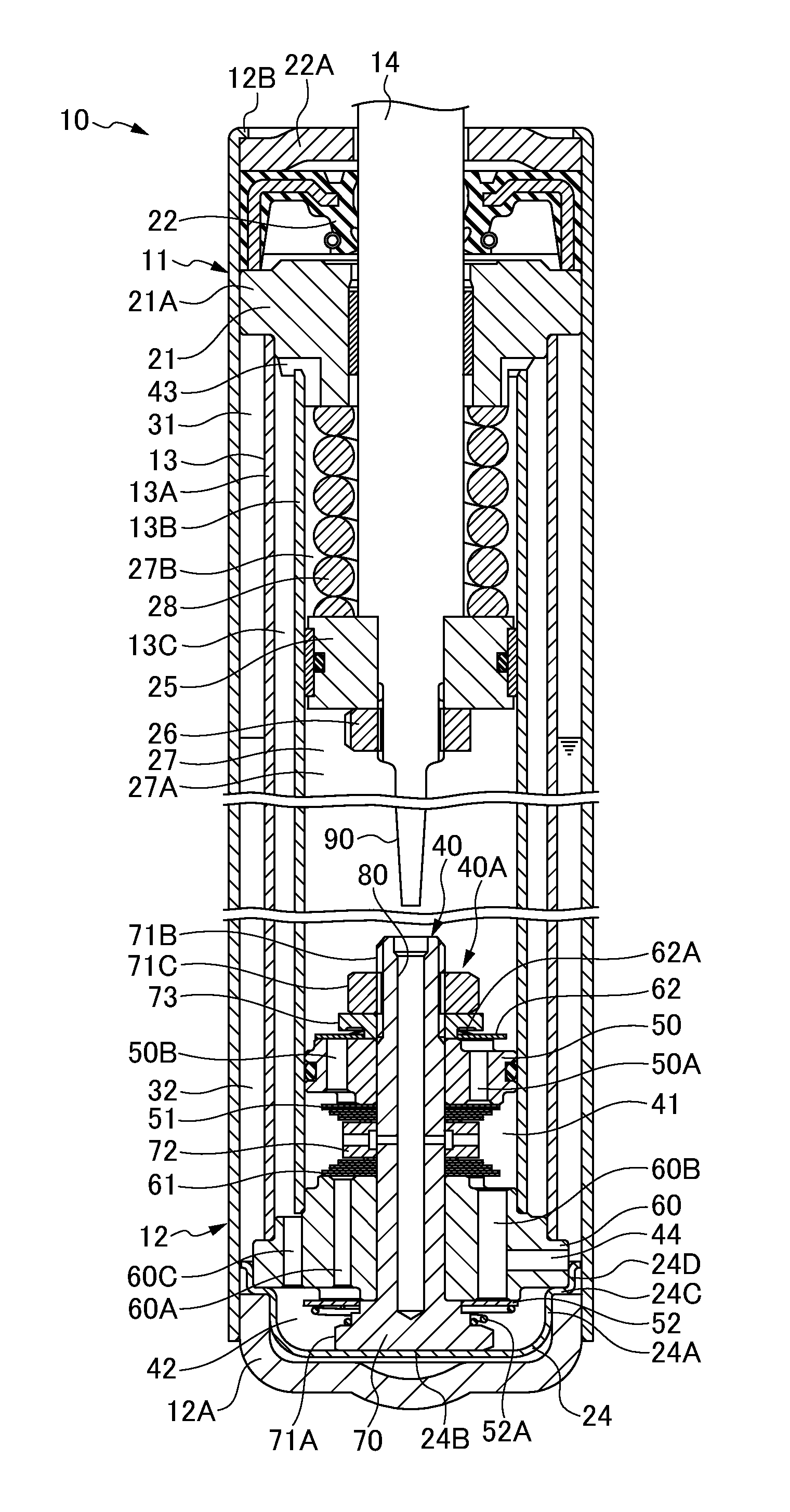
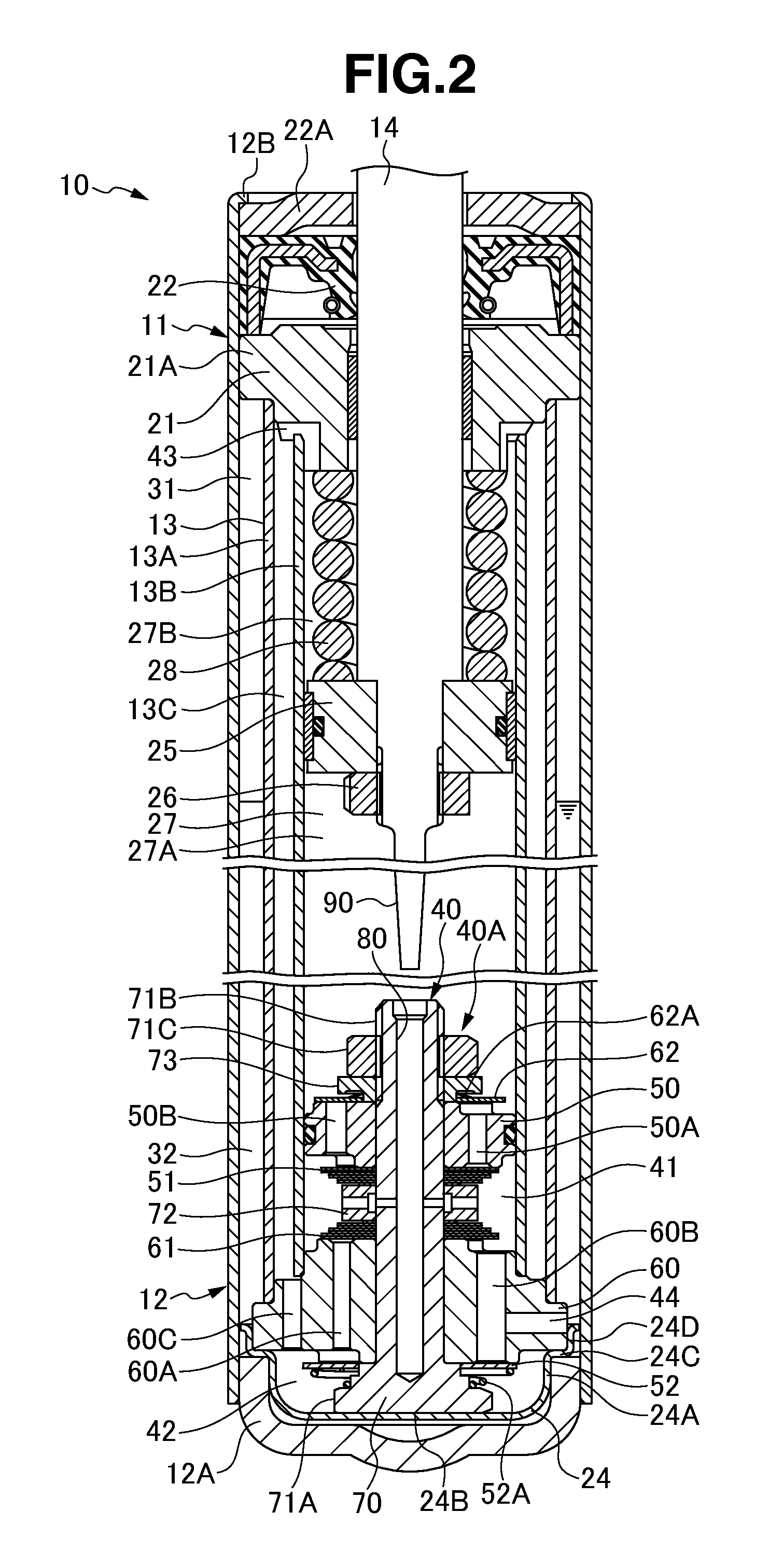
[0053]A hydraulic shock absorber 10 is structured, as shown in FIGS. 1 to 3, such that a damper case 11 attached to an axle side has a damper tube 12, and a damper cylinder 13 is inserted and fitted into an inner portion of the damper tube 12. Further, the hydraulic shock absorber 10 is structured such that a piston rod 14 attached to a vehicle body side is slidably inserted into a center portion of the damper tube 12 of the damper case 11 and the cylinder 13, and a suspension spring 15 is interposed to an outer portion of the damper case 11 and the piston rod 14.
[0054]The damper case 11 is provided with an axle side attaching member 16 in a center portion of an outer face of a bottom cap 12A of the damper tube 12, and the piston rod 14 is provided with a vehicle body side attaching member 17. A spring receiver 18 is provided in an outer peripheral portion of the damper tube 12 in the damper case 11, and a spring receiver 19 is provided in an outer peripheral portion of...
second embodiment
FIGS. 6 to 9B
[0103]In a hydraulic shock absorber 10 in accordance with a second embodiment, the following structure is provided for applying a position dependency to the damping force generated by the compression side damping valve 51 and the extension side damping valve 61 of the damping force generating device 40, easily increasing the damping force generated by the compression side damping valve 51 and the extension side damping valve 61, and increasing the change (the position dependency) according to the strokes of the damping forces.
[0104]In other words, the damping force generating device 40 of the hydraulic shock absorber 10 is provided in a side wall of the inner tube 13B of the cylinder 13 with a through-hole 100 which communicates the piston side oil chamber 27A of the cylinder 13 with the rod side oil chamber 27B via the outer flow path 13C. Further, the through-hole 100 can be opened and closed by the outer peripheral portion of the piston 25 according to the forward an...
PUM
 Abstract
Description
Claims
Application Information