Passive damper

a damper and passive technology, applied in the direction of spring/damper, shock-proofing, mechanical equipment, etc., can solve the problems of prone to malfunction, expensive and complicated active dampers, and need extensive maintenan

Active Publication Date: 2014-06-26
DAMPTECH AS
View PDF13 Cites 10 Cited by
  • Summary
  • Abstract
  • Description
  • Claims
  • Application Information

AI Technical Summary

Benefits of technology

[0006]On this background, it is an object of the present application to provide a passive damper for dampening relative movement between members of a structure to which the damper can be connected that has a damper characteristic or impedance that changes with the amplitude of the oscillations or with magnitude of the movement that it is exposed to.

Problems solved by technology

If such displacements are large, or if they occur periodically, they may have serious impact on the conditions of the structure, and may cause severe damages or even result in a collapse.
The active dampers are expensive and technically complicated devices, which need extensive maintenance in order to work when needed.
Further, they are prone to malfunctions, e.g. leaking of hydraulic fluids or breakdown of electronic control systems.
However, this can only be done during installation or during service, and not in response to an event such as a seismic event.
Passive dampers with a variable damping characteristics are sometimes desirable but no commercially viable dampers of such kind are presently available.

Method used


Image

  • Passive damper
  • Passive damper
  • Passive damper

Examples


Embodiment Construction

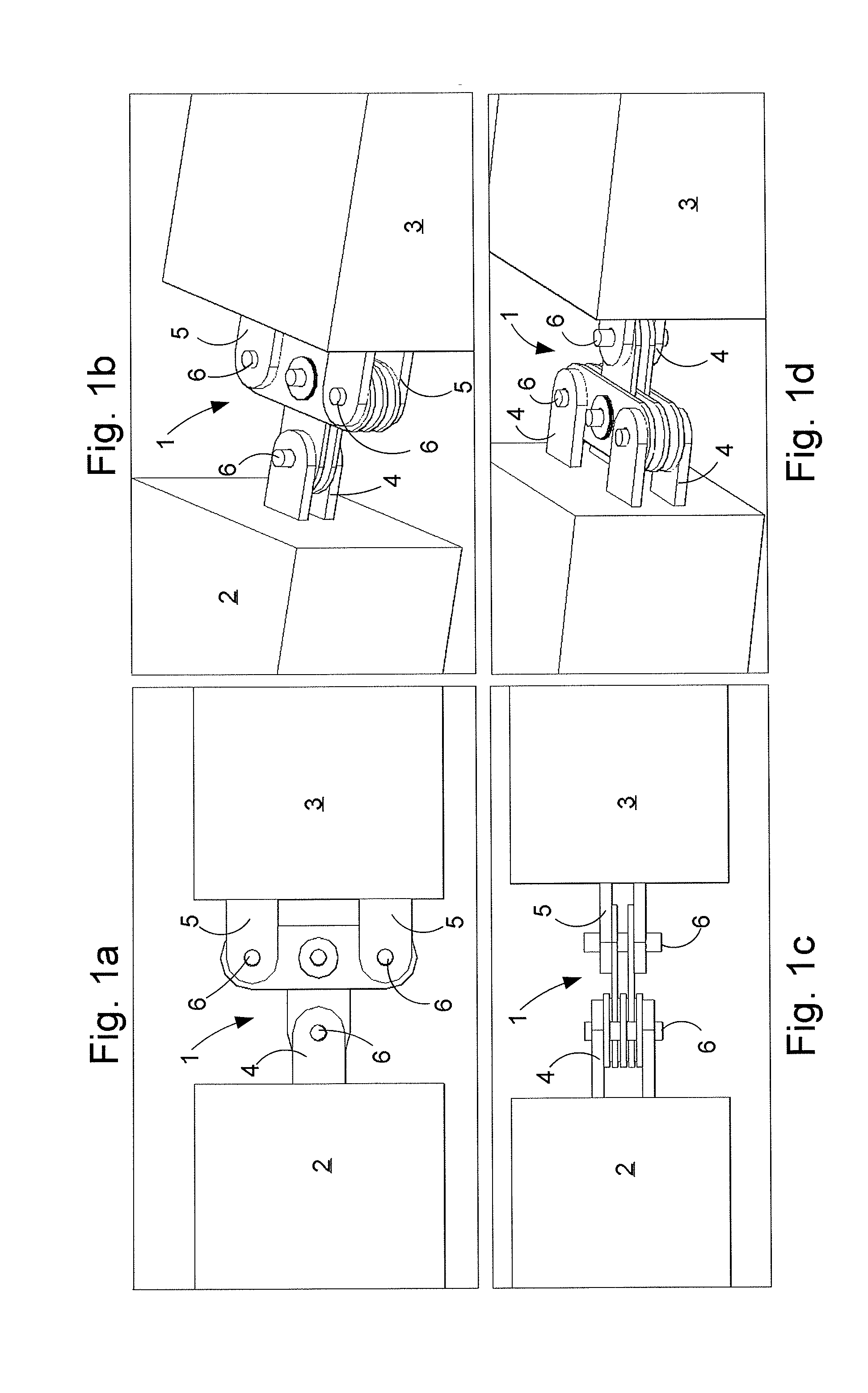
[0034]Below follows a description of embodiments of the present invention, referring to the figures. In the below description, a member of a structure, such as a building, is understood to include e.g. pillars, beams, stiffeners, stretchers, v-braces and the like, and any member which maintains the rigidity of a structure of a construction or structural body of e.g. a building or the like.

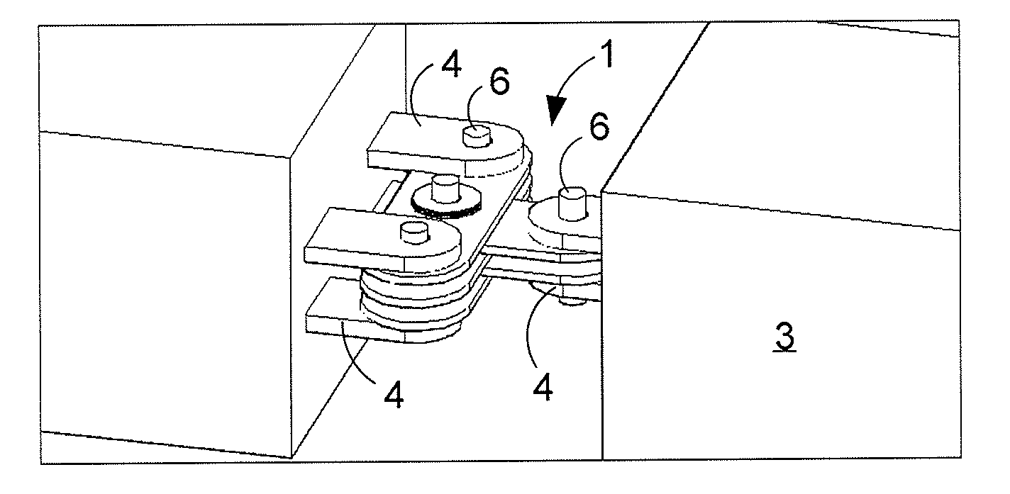
[0035]With reference to FIGS. 1a to 1d a damper 1 according to an exemplary embodiment is shown connected to members 2, 3 of a structure, such as a building. The damper 1, in this embodiment is substantially T-shaped. Each end of the T-shaped damper is connected to the structure. The two opposite ends to the “top” or horizontal line of the T are connected via respective pins 6 and brackets 5 to member 3 of the structure. The free end of the “leg” or vertical line of the T is connected via a pin 6 and a bracket 4 to member 2 of the structure.

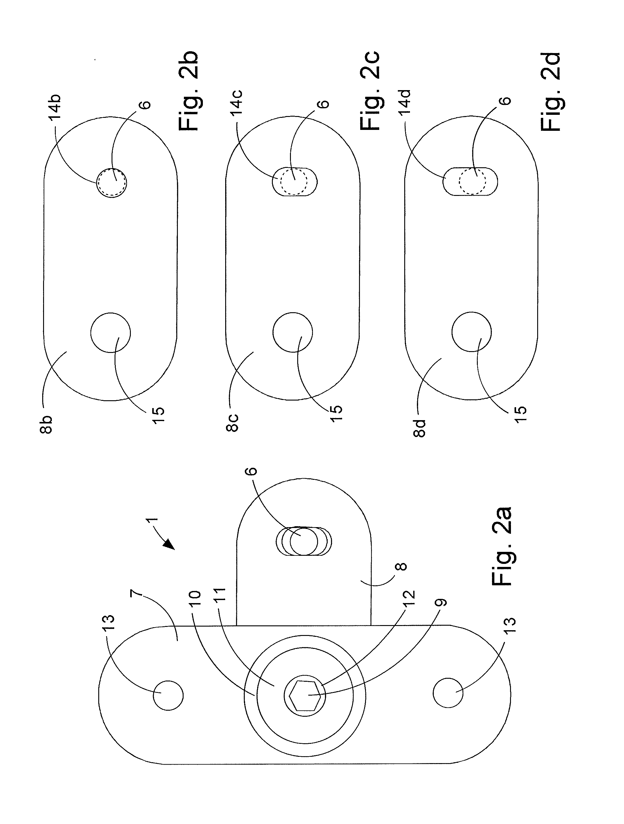
[0036]With reference to FIGS. 2a-2d, 3a-3d and 4a-4d the d...


PUM


Abstract

A passive damper (1) with a first set (7) of parallel disposed plates (7a) and a second set (8) of parallel disposed plates (8b,8c,8d), that overlap one another in an alternating fashion at a rotational joint with damping pads (15) between the plates (7a,8b,8c,8d). The rotational joint comprises a pin or bolt (9) inserted through apertures (15) in the plates (7a,8b,8c,8d) and there is a connection hole (14b) in each of the plates of the second set (8) of plates for receiving a connection pin (6) therein for connecting the second set of plates (8) to a members (2,3) of a structure. The connection holes (14c,14d) in a selection of the plates (8c,8d) of the second set (8) of plates is shaped and dimensioned to provide a predetermined amount of clearance with said connection pin (6) so that the connection pin (6) can move inside the connection holes (14c,14d) of the selection of plates (8c,8d) to a predetermined extent without the selection of plates (8c,8d) taking part in the damping action of the damper (1).

Description

[0001]The present invention relates to a damper that can be used to protect a structure or a structural system, e.g. a building against dynamic stress such as the stress caused by an earthquake, the shock of a large sea wave, or a stress that is produced by vibration and the like caused by shocks from transportation, machines, wind, or the like. More specifically, the invention relates to a damper that can operate with different damping forces for different displacement magnitudes.BACKGROUND OF THE INVENTION[0002]When a structure or structural system is excited, elements of the structure may get displaced relative to one another. If such displacements are large, or if they occur periodically, they may have serious impact on the conditions of the structure, and may cause severe damages or even result in a collapse.[0003]Dampers play an important role in the protection of structures such as buildings, and they exist in numerous variants. Dampers are typically damping the motion by mea...

Claims


Application Information

Patent Timeline
Patent Type & Authority Applications(United States)
IPC IPC(8): E04B1/98E04H9/02
CPCE04B1/98E04H9/022E04B1/985E04H9/021F16F15/02F16F2222/04F16F2230/0023F16F2238/04E04H9/0215F16F1/40
Inventor MUALLA, IMAD H.
Owner DAMPTECH AS
Why Eureka
Try Eureka