
Eureka
For R&D, Eureka makes reading and utilizing patents & technical documents easy.
Eureka AIR
Designed for self-driven R&D workflows. Generate viable solutions, solve complex R&D challenges, empower your innovation with AI.

Eureka Materials
Designed for material experts only. Revolutionize your material R&D, from search, analyze, to developing new materials.

TechResearch
Generate reliable direction feasibility study reports for your R&D in just a few steps.

TechSeek
Discover and master advanced knowledge NOW. Basics, ideas, possibilities, all at once.

TechMind
As an expert in R&D Theories, TechMind can generates customized viable solutions instantly.

TechRisk
Analyze your overall solution with one click, know your potential R&D risks in advance.

TechMonitor
Get weekly tech updates, stay abreast of the latest tech innovations and key insights.
Chair with tilting backrest
a backrest and chair technology, applied in the field of chairs with a tilting backrest, can solve the problems of dangerous failure points, pinched users or their/her garments, etc., and achieve the effect of being valid and solid
- Summary
- Abstract
- Description
- Claims
- Application Information
AI Technical Summary
Benefits of technology
Problems solved by technology
Method used
Image

Examples
first embodiment
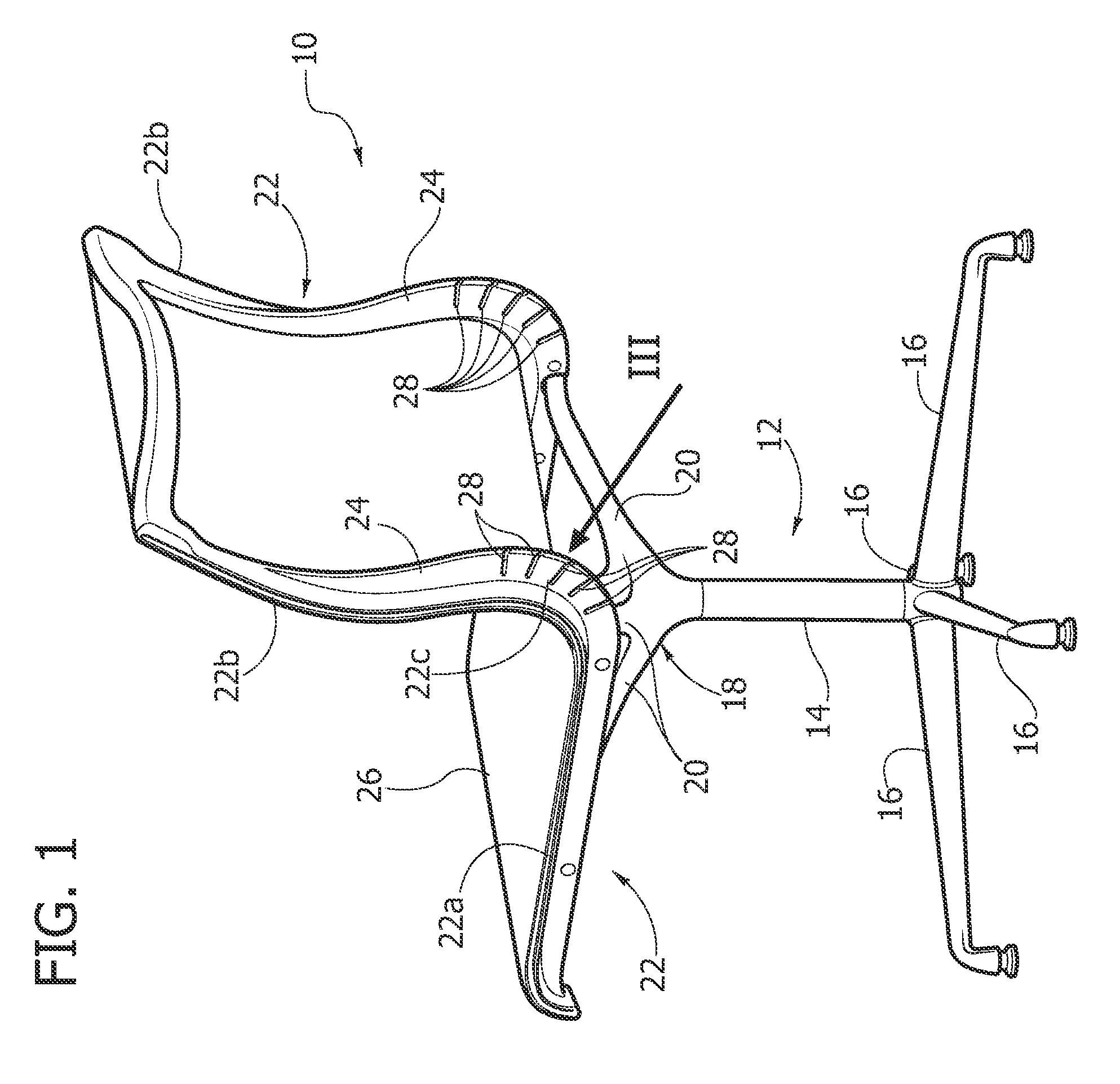
[0014]With reference to FIG. 1, designated by 10 is a chair according to the present invention. The chair 10 comprises a base structure 12 including a vertical upright 14 that rests on the floor by means of a plurality of radial arms 16. The central upright 14, which is possibly height-adjustable, carries at its top end a support 18, provided, for example, with two pairs of radial arms 20.
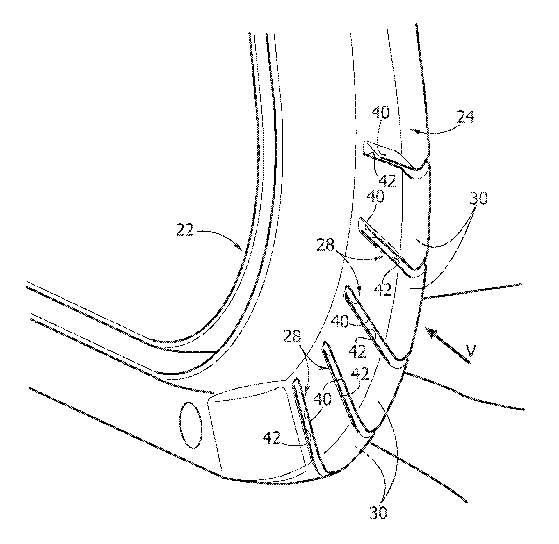
[0015]The chair 10 comprises two supporting sectional elements 22 forming the lateral edges of the chair 10, fixed to the outer ends of the radial arms 20. The two supporting sectional elements 22 are parallel to and set at a distance from one another in a transverse direction. The two supporting sectional elements 22 are preferably specular, and each of them is substantially L-shaped, with a seat portion 22a, a backrest portion 22b, and an arched radiusing portion 22c, which extends between the seat portion 22a and the backrest portion 22b.
[0016]Each supporting sectional element 22 is preferably ...
second embodiment
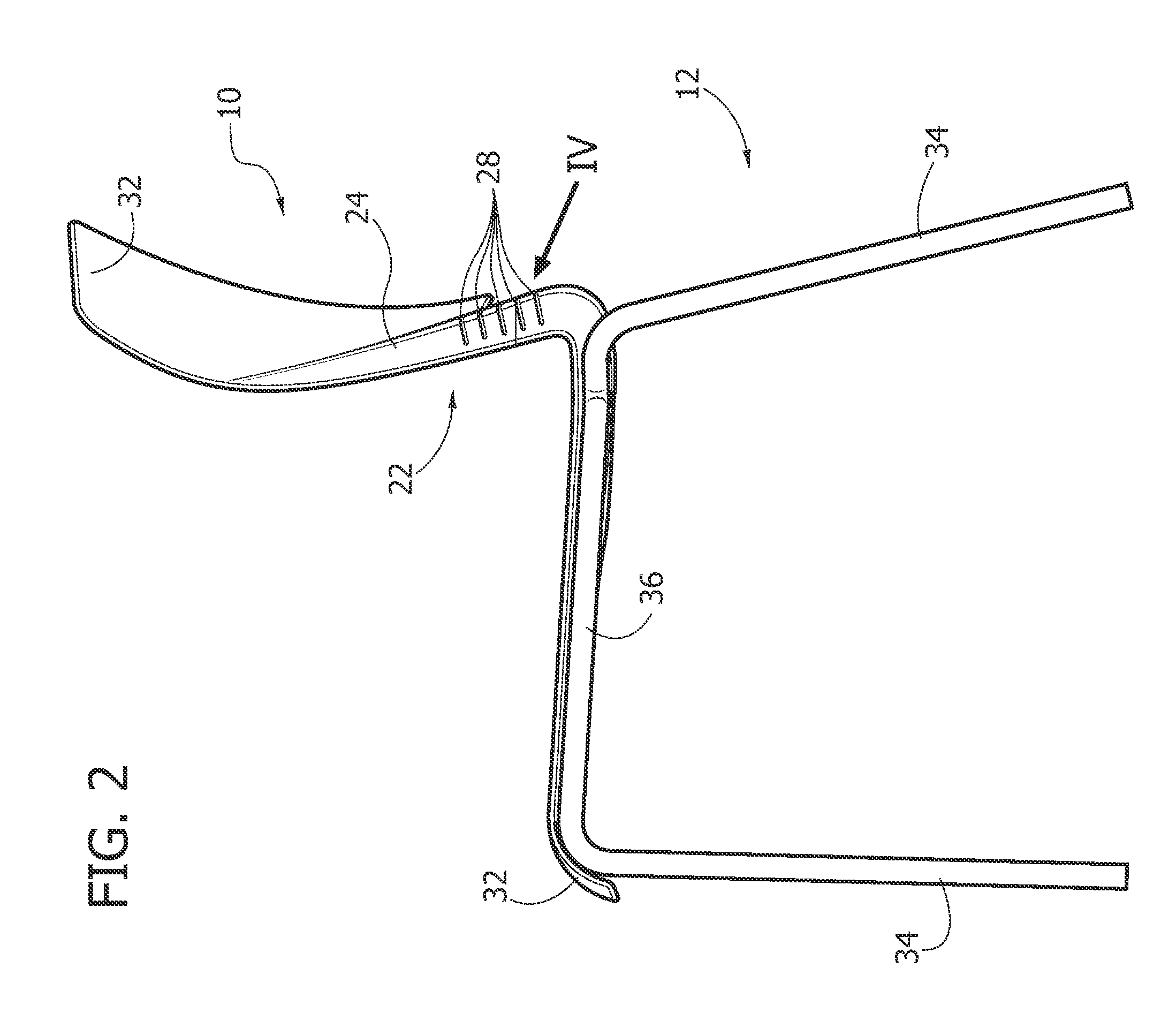
[0020]FIGS. 2 and 4 illustrate the chair 10 according to the present invention. The elements corresponding to the ones described previously are designated by the same reference numbers.
[0021]In this case, the seat and the backrest of the chair 10 are formed by a shaped thin plate 32 of injection-moulded plastic material, formed integrally with the lateral supporting sectional elements 22. Also in this case, the supporting sectional elements 22 are provided with respective ribbings 24 provided with notches 28 that form points of localized bending of the supporting sectional elements 22.
[0022]In the variant of FIGS. 2 and 4 the base structure 12 of the chair 10 can be formed by a metal frame with four legs 34, having two lateral elements 36, fixed to which are the respective supporting sectional elements 22.
[0023]Shown in FIG. 4 is a seat 38 formed at the base of the ribbing 24, in which there can be housed an elastic member, constituted for example by a bar of metal material with hig...
PUM
 Abstract
Description
Claims
Application Information
 - R&D Engineer
- R&D Manager
- IP Professional
- Industry Leading Data Capabilities
- Powerful AI technology
- Patent DNA Extraction
Browse by: Latest US Patents, China's latest patents, Technical Efficacy Thesaurus, Application Domain, Technology Topic, Popular Technical Reports.
© 2024 PatSnap. All rights reserved.Legal|Privacy policy|Modern Slavery Act Transparency Statement|Sitemap|About US| Contact US: help@patsnap.com