Machine and method for manufacturing composite filters

a technology of composite filters and machines, applied in tobacco smoke filters, food science, tobacco, etc., can solve the problems of affecting the operation of the machine, and canceling the effect of retaining the other, so as to achieve optimal operation of the garniture tongue

Inactive Publication Date: 2015-03-31
GD SPA
View PDF16 Cites 8 Cited by
  • Summary
  • Abstract
  • Description
  • Claims
  • Application Information

AI Technical Summary

Benefits of technology

[0023]The aim of this invention is to provide a machine and a method such as will be unaffected by the above mentioned drawback, that is to say, such as can guarantee the optimum operation of the garniture tongue.
[0024]Another aim of the invention is to provide a machine whereby any relative phase difference between the two filter rods at the cutting element can be easily eliminated.

Problems solved by technology

One problem with this machine arises if the relative misalignment between the two rods is too high, that is to say, greater than a predetermined value.
In this condition, when the rotating member simultaneously transfers the two filter groups to the conveyors of the garniture tongue, one of the two filter groups being released may excessively compress the other groups already present on the conveyors and fall out of the flute on the rotating member, thus cancelling the effect of retaining the other filter group in the other flute.
As a result, one or more filter groups are missing from the filter rod supplied to the garniture tongue and in the worst cases this may even cause a machine shutdown to allow the fault to be corrected.
This is worsened by the fact that the problem occurs relatively frequently because the filter segments supplied to the reservoirs have variable dimensions (typically of the order of a few tenths of a millimeter) on account of production tolerances.
As a result, during machine operation, the two filter rods tend to go out of phase with each other and this can only be partly compensated by adjusting the relative speed of the garniture tongue conveyors.

Method used


Image

  • Machine and method for manufacturing composite filters
  • Machine and method for manufacturing composite filters
  • Machine and method for manufacturing composite filters

Examples


Embodiment Construction

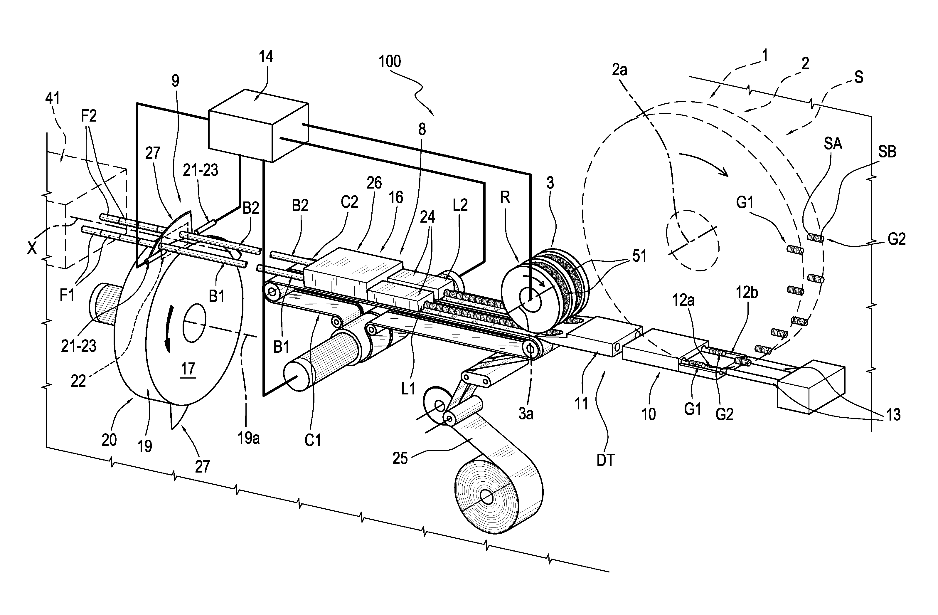
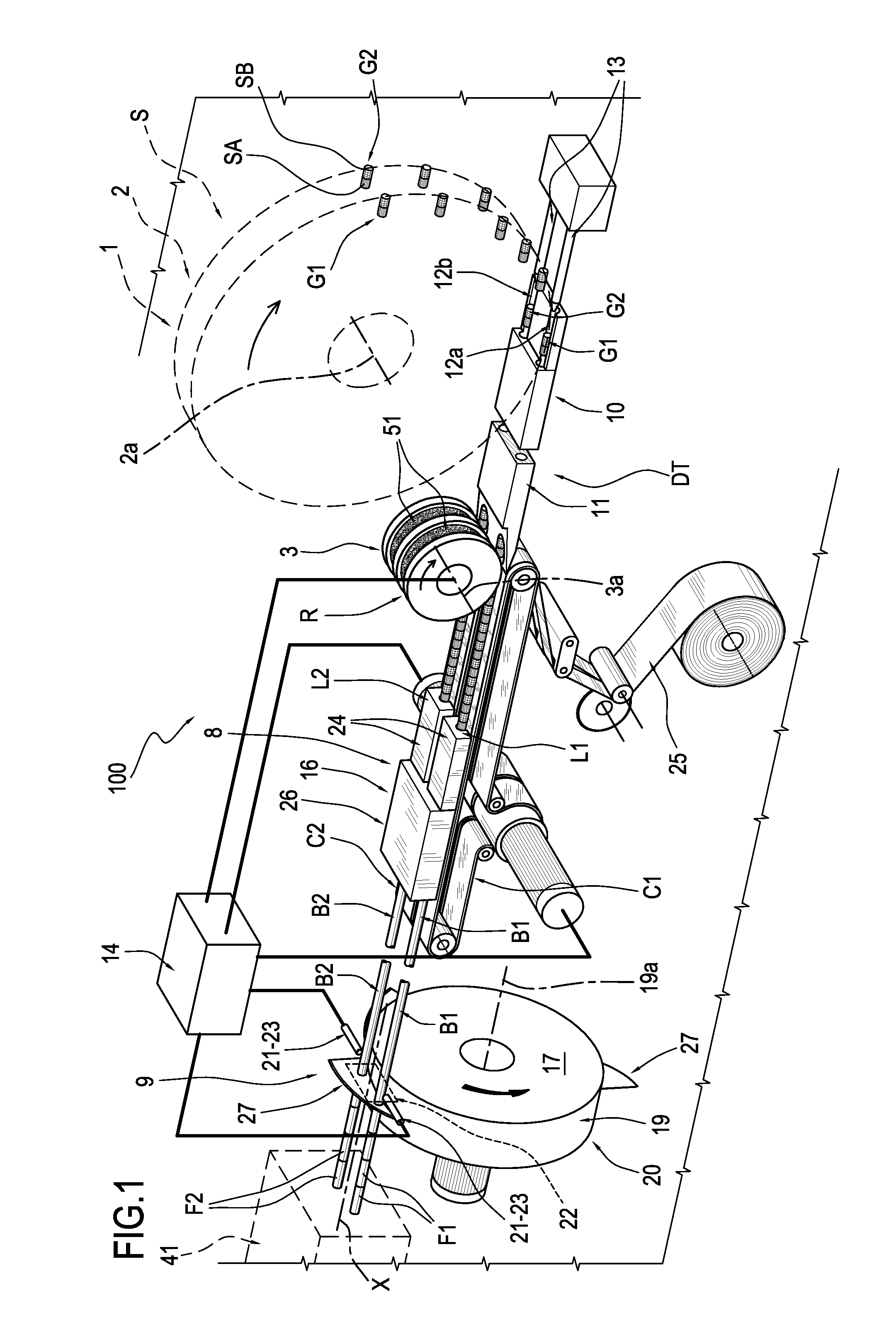
[0033]With reference to the accompanying drawings, the numeral 100 denotes in its entirety a machine for making composite filters from two or more filter plugs.

[0034]The term “filter plug” as used herein means a piece of substantially uniform filter material, obtained preferably by cutting a segment of filter material. In other words, a filter plug is a portion of a segment of filter material.

[0035]The term “filter group” as used herein means a group of filter plugs of different types, that is to say, made of different materials and / or having different filtration properties, lined up longitudinally with each other.

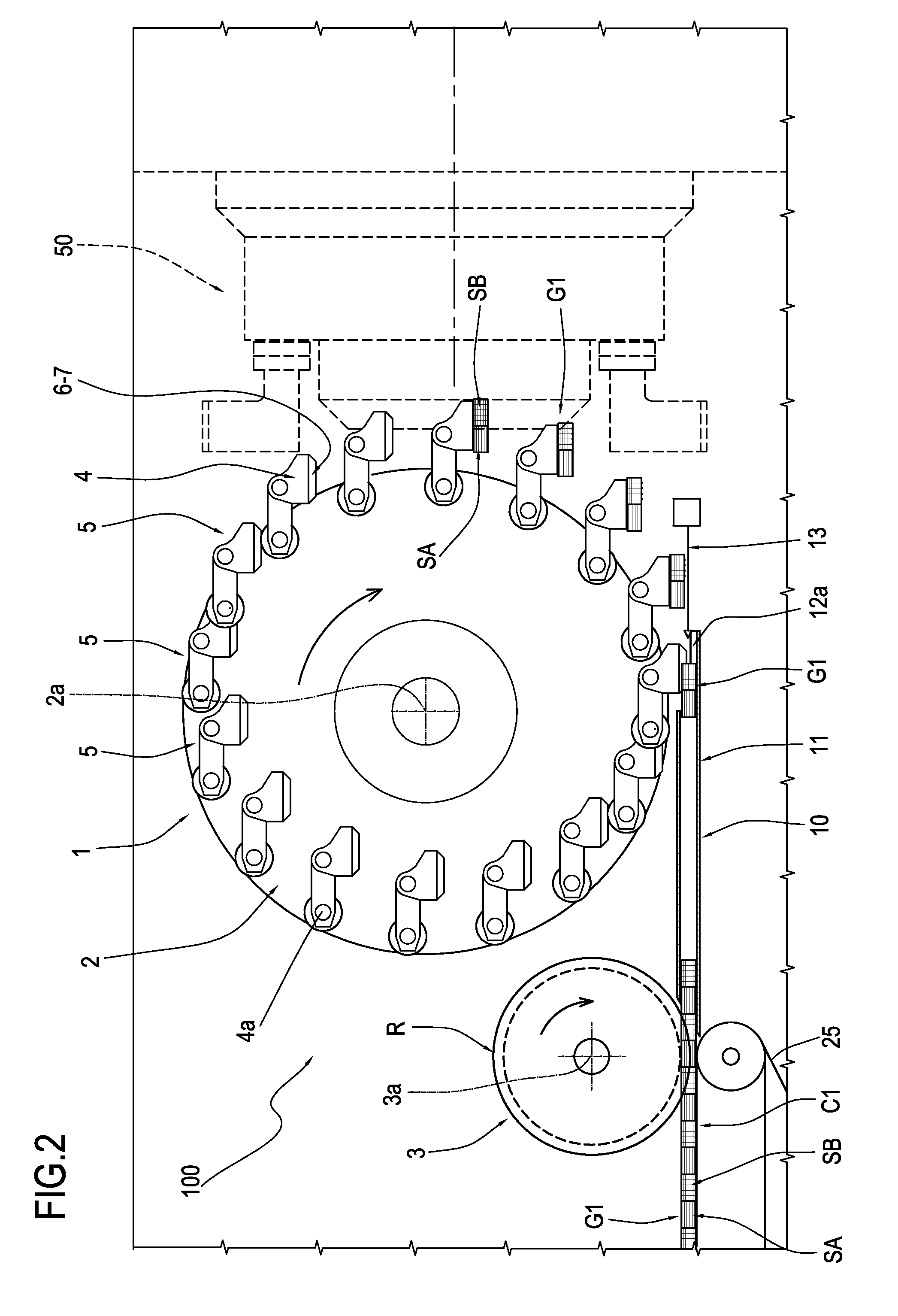
[0036]The machine 100 comprises a rotating member, denoted by the reference numeral 1.

[0037]The rotating member 1, which is of substantially known type, is described in patent document EP1787534 in the name of the same Applicant as this invention and incorporated herein by reference.

[0038]The rotating member 1 is represented schematically in FIG. 1 and is shown more clearl...


PUM


Abstract

In a machine and a method for manufacturing composite filters (F1, F2) for cigarettes or the like, a feed conveyor (S) supplies filter groups (G1, G2) in pairs to two respective feed lines (L1, L2) of a station (16) for forming two continuous filter rods (B1, B2); the machine (100) comprises at least one transfer device (DT) by which the filter groups (G1, G2) are taken up from the feed conveyor (S) and directed along the feed lines (L1, L2), and at least one release device (R), operating along the two feed lines (L1, L2), by which the two filter groups (G1, G2) are taken up from the transfer device (DT) and released in phase one with another along the selfsame feed lines (L1, L2); the rate at which the filter groups (G1, G2) are released by the release device (R) is governed according to the phase value of at least one of the continuous filter rods (B1, B2) relative to the cyclic cutting operation whereby the two filter rods (B1, B2) are cut transversally to make the composite filters (F1, F2).

Description

[0001]This application claims priority to Italian Patent Application B02010A000433 filed Jul. 8, 2010, the entirety of which is incorporated by reference herein.BACKGROUND OF THE INVENTION[0002]This invention relates to a machine and a method for manufacturing composite filters, that is to say, filters comprising two or more filter plugs.[0003]The term “composite filter” means a cigarette filter obtained by joining end-to-end two or more filter plugs having different filtration properties and / or made of different materials.[0004]Document EP1787534, in the name of the same Applicant as this invention, discloses a twin-track machine for manufacturing composite filters. It involves dividing up at least two segments of filter material, supplied to respective reservoirs, to make filter plugs from them.[0005]These filter plugs are transferred along a direction transverse to their longitudinal axes by a train of rotating transfer rollers of known type.[0006]The machine comprises an assembl...

Claims


Application Information

Patent Timeline
Patent Type & Authority Patents(United States)
IPC IPC(8): B31C99/00A24D3/02
CPCA24D3/0287A24D3/0295
Inventor RIGHETTI, MARIOSTAGNI, ALBERTOSARTONI, MASSIMO
Owner GD SPA
Why Eureka
Try Eureka