
Magnetic resonance imaging apparatus, evaluation device, and method

a magnetic resonance imaging and evaluation device technology, applied in the field of magnetic resonance imaging apparatus, evaluation device, and method, can solve the problems of non-uniform brightness distribution, incorrect information, diffraction effect and transmission characteristic distortion, etc., to achieve cost-effective, high-efficiency image acquisition, and the effect of reducing the cost of operation

Active Publication Date: 2015-03-31
SIEMENS HEALTHCARE GMBH
View PDF23 Cites 5 Cited by
  • Summary
  • Abstract
  • Description
  • Claims
  • Application Information

AI Technical Summary

Benefits of technology

[0046]A particular advantage of the invention is that it can be realized cost-effectively and / or be integrated without high cost into existing systems.
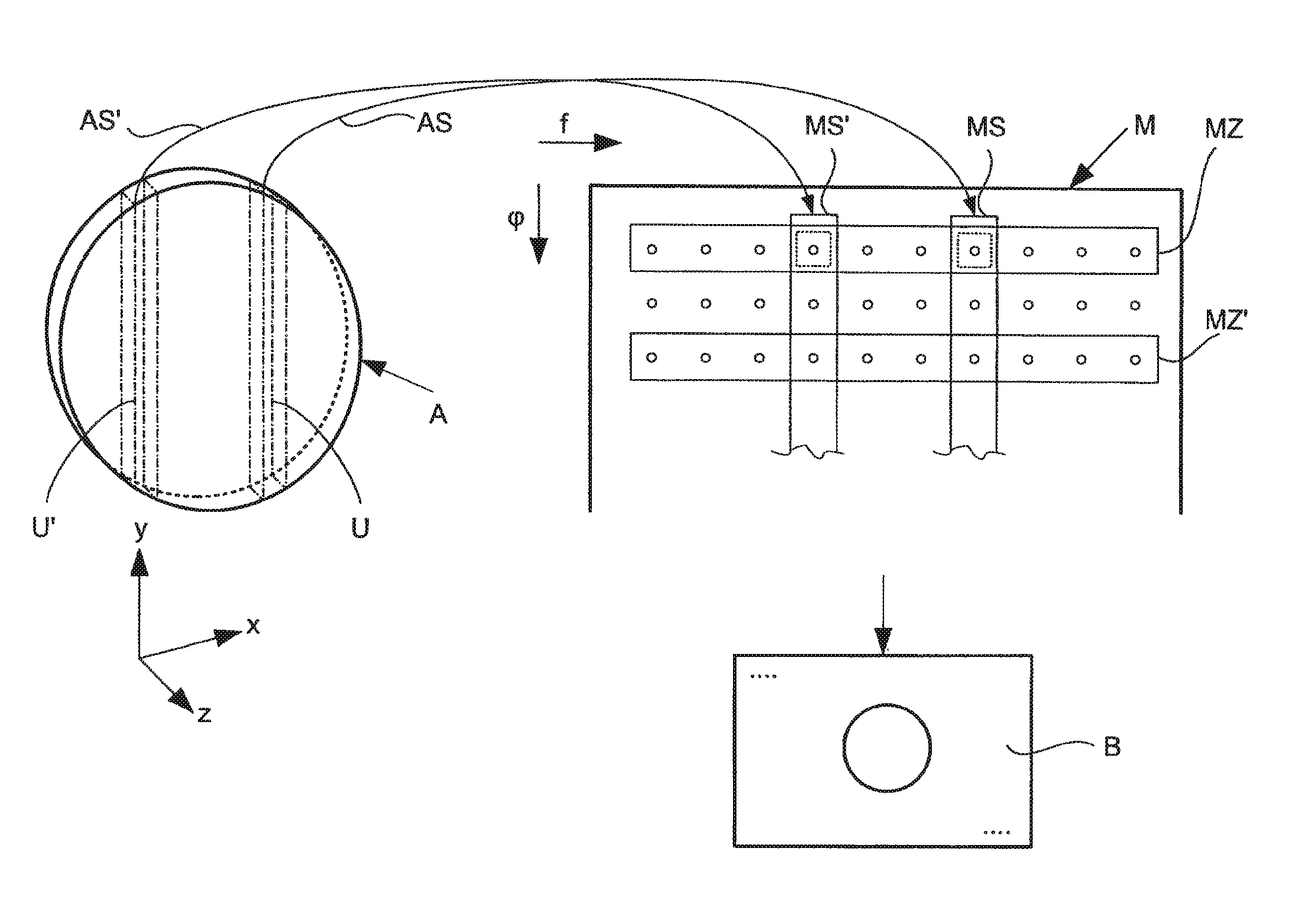
[0047]An additional advantage of the invention is that the problems in the image acquisition that result from inhomogeneities of the excitation signal or the transmission characteristic can be reduced, minimized or compensated. In particular given the use of high magnetic field strengths, diffraction effects can lead to shadows, thus (in connection with the excitation of nuclear spins) to sub-regions of the excitation region with reduced, intensified or non-uniform excitation. According to the invention, the nuclear spins are excited a second time, advantageously in the same excitation region, and with a second transmission mode that is different from the first, so regions that are potentially shadowed in the first transmission mode are excited in the second transmission mode and vice versa. It is thus advantageously possible to generate an image using both response signals, which image has reduced or no shadows and / or a significantly better homogeneity.
[0048]The transmission modes advantageously differ with regard to the excitation signal, the transmission characteristic and / or the (B1) field distribution, and in particular in a spatial dependency of the excitation of the nuclear spins in the excitation region.
[0049]Different excitation or transmission signals are advantageously used in the transmission modes, in particular with regard to the phase position and / or the amplitude. The use of different excitation or transmission signals enables a variation of the transmission characteristic and hereby advantageously enables a generation of different transmission modes without mechanical modifications or the like having to be made at the transmission device, for example (which is also possible, however).
[0050]A multichannel transmission method—in particular RF shimming or Transmit SENSE (as explained in the preceding)—is advantageously used to generate different transmission modes. Different transmission characteristics can advantageously be generated particularly simply and quickly via multichannel transmission methods or multiple transmission devices, in particular transmission devices that can be activated at least partially independently of one another.
[0051]Additionally, field distributions or transmission characteristics that are different in the transmission modes can be generated particularly simply in that at least two transmission devices are activated with different transmission signals.

Problems solved by technology

A non-uniform excitation of the excitation region or more or less excited or, respectively, shadowed sub-regions in the excitation region lead to a non-uniform brightness distribution or even to incorrect information in the resulting image.
In particular, this leads to diffraction effects and distortions of the transmission characteristic.
This results in a non-uniform and / or insufficient excitation of the nuclear spins in the excitation region.
However, given the use of high magnetic field strengths the method is in particular not in the position to sufficiently reduce shadows.
These methods are also called “Transmit Sensitivity Encoding” or “Transmit SENSE” but are significantly more complicated in comparison to RF shimming.
A similarly complicated determination of the properties of each individual transmission device in advance of each measurement is required for calibration, which leads to time losses in the measurement.
The known method does not address an image generation with multiple transmission modes, nor is the large system cost to implement Transmit SENSE reduced.
However, shadows can also not be effectively prevented or compensated with this method.
An additional limiting factor in MRT is the acquisition time necessary to achieve high-resolution images.
Conversely, complicated and expensive devices as well as complex signal processings are required to implement such methods.

Method used


Image

  • Magnetic resonance imaging apparatus, evaluation device, and method
  • Magnetic resonance imaging apparatus, evaluation device, and method
  • Magnetic resonance imaging apparatus, evaluation device, and method

Examples


Embodiment Construction

[0073]In the figures the same reference characters are respectively used for the same parts and components, wherein corresponding advantages and properties result even though a repeat description is omitted.

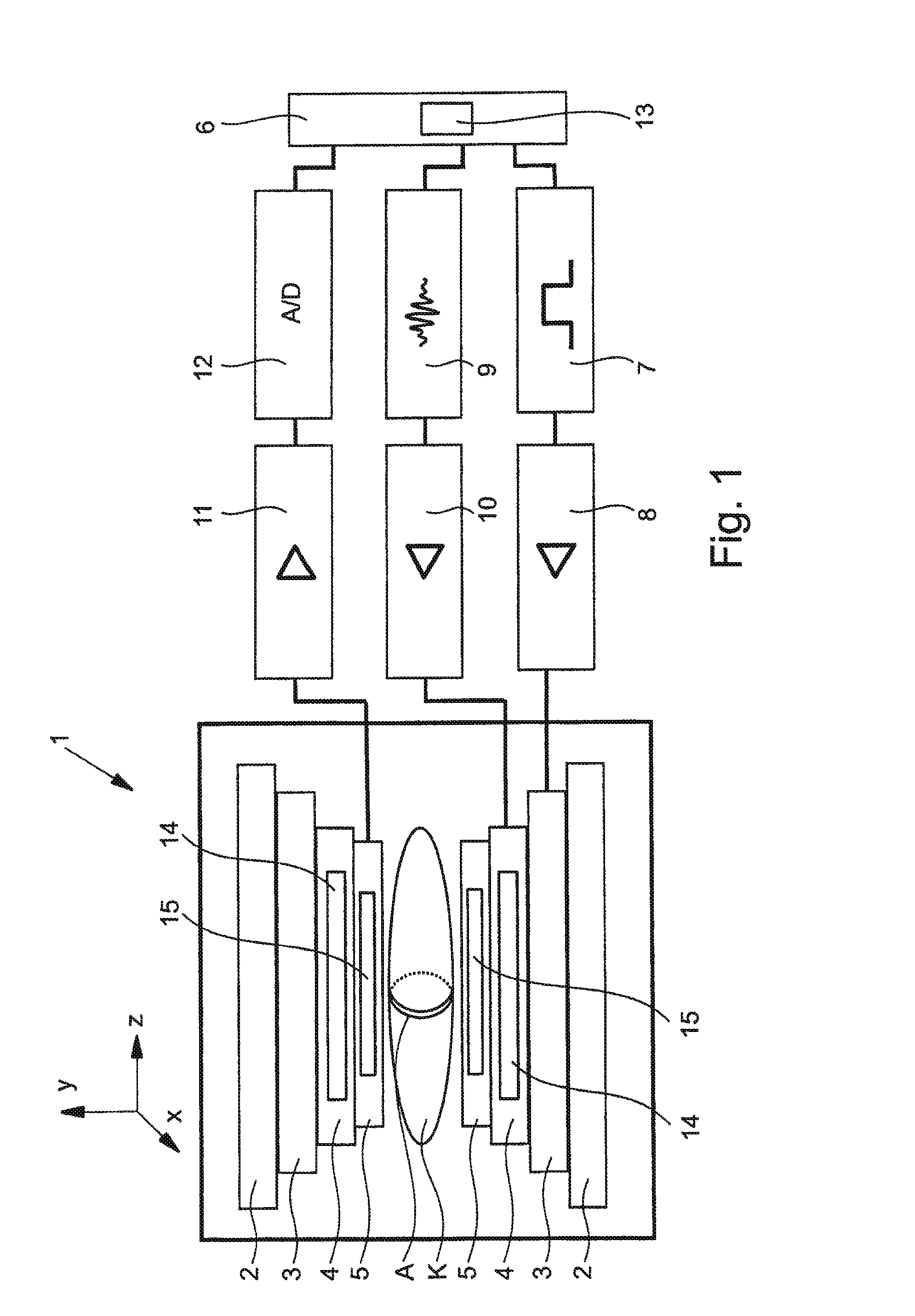
[0074]FIG. 1 shows a schematic design of a magnetic resonance tomography apparatus 1 with a basic magnet 2 to generate a basic magnetic field, gradient coils 3 to generate gradient fields, and a transmission device 4 to generate at least one excitation signal in the aforementioned sense, in particular to excite nuclear spins in an excitation region A of a body K to be examined (in particular of an animal or person). The tomography apparatus 1 advantageously has an acquisition device 5 to acquire response signals AS of the nuclear spins, as was already addressed in the preamble.

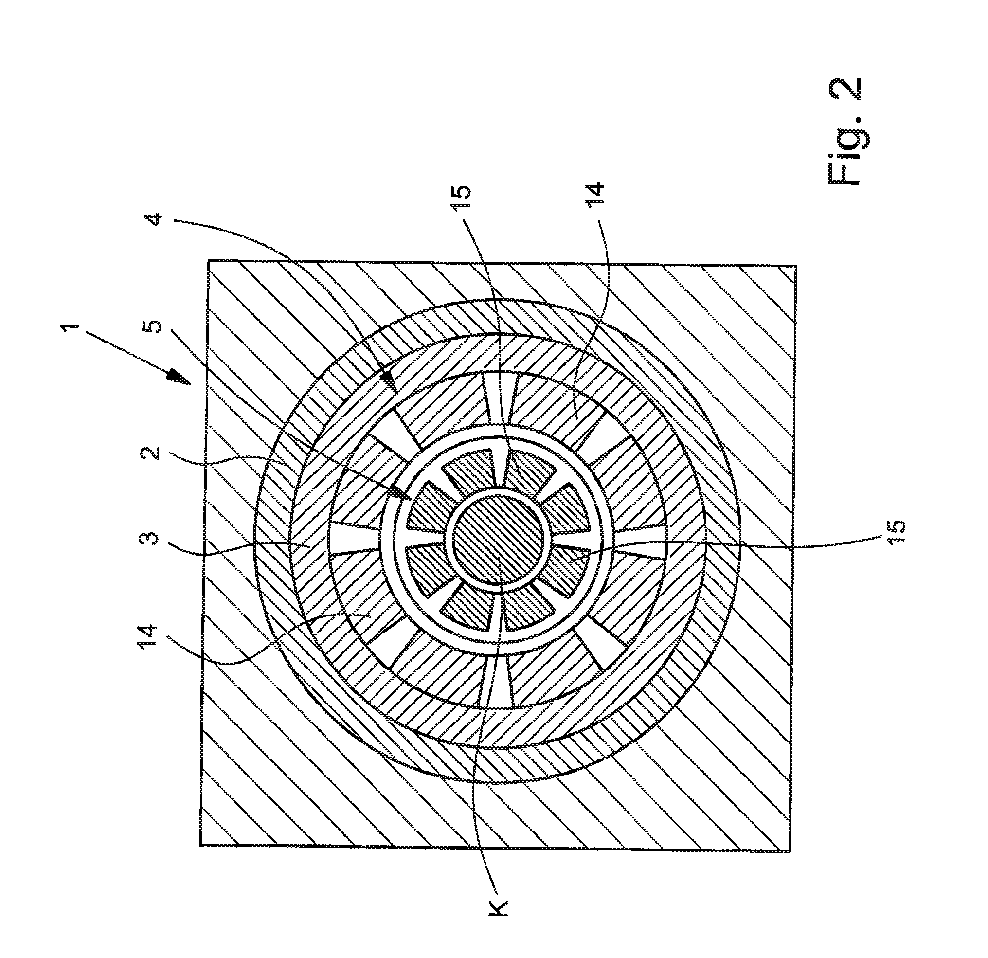
[0075]FIG. 2 shows an abstracted section of the tomography apparatus 1 with the transmission device 4, which advantageously has multiple (here eight) transmission devices 14 and with an acquisition device 5...


PUM


Abstract

An image is generated from data acquired with a magnetic resonance tomography, wherein nuclear spins in an excitation region are excited with different transmission modes and a common image is generated from the response signals.

Description

BACKGROUND OF THE INVENTION[0001]1. Field of the Invention[0002]The present invention concerns a method to generate an image with a magnetic resonance tomography apparatus and an evaluation device, as well as a magnetic resonance tomography apparatus.[0003]2. Description of the Prior Art[0004]Magnetic resonance tomography (abbreviated as MRT) has for many years represented one of the central imaging methods of biophysics and medicine.[0005]MRT is based on the alignment of nuclear spins (in particular that of H atoms) in a body by means of a strong, stationary magnetic field (also called a B0 field or basic magnetic field). The nuclear spins can be deflected out of their alignment or can be affected in their alignment by energy supplied to them at a specific resonance frequency (known as the Larmor frequency) dependent on an external magnetic field (such as the B0 field).[0006]Excited spins release energy again and generate a measurable field or response signal. The response signal e...

Claims


Application Information

Patent Timeline
Patent Type & Authority Patents(United States)
IPC IPC(8): G01R33/44G01R33/561G01R33/565
CPCG01R33/5612G01R33/5659
Inventor BITZ, ANDREASMADERWALD, STEFANORZADA, STEPHANPOSER, BENEDIKT
Owner SIEMENS HEALTHCARE GMBH
Learn More