Wafer handling apparatus

a technology of handling apparatus and wafer, which is applied in the direction of lifting devices, hoisting equipments, semiconductor devices, etc., can solve the problems of wafers on hard polymer pads slipping sideways off the end effector apparatus, and contaminating the parent metal of the end effector finger of the wafer, so as to prevent slippage

Active Publication Date: 2015-04-14
VARIAN SEMICON EQUIP ASSOC INC
View PDF14 Cites 4 Cited by
  • Summary
  • Abstract
  • Description
  • Claims
  • Application Information

AI Technical Summary

Problems solved by technology

If the silicon wafer were contacted by a metallic end effector finger, the wafer could be contaminated with the parent metal of the end effector finger.
If such a hard polymer pad supporting a wafer along an end effector finger is rotated too rapidly, the wafer can slip sideways off the end effector apparatus.
Wafers on hard polymer pads can also slip during linear motion events when the end effector vibrates or the robot control system is not tuned properly causing the end effector fingers to also vibrate.

Method used


Image

  • Wafer handling apparatus
  • Wafer handling apparatus
  • Wafer handling apparatus

Examples


Embodiment Construction

[0017]The present invention will now be described more fully hereinafter with reference to the accompanying drawings, in which preferred embodiments of the invention are shown. This invention, however, may be embodied in many different forms and should not be construed as limited to the embodiments set forth herein. Rather, these embodiments are provided so that this disclosure will be thorough and complete, and will fully convey the scope of the invention to those skilled in the art. In the drawings, like numbers refer to like elements throughout.

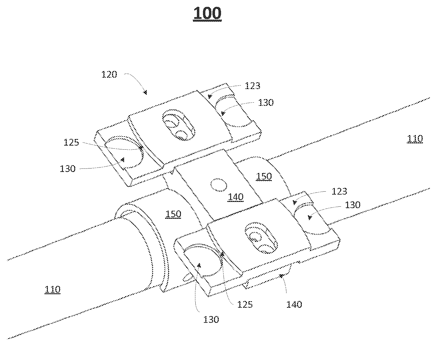
[0018]FIG. 1 is an illustration of one embodiment of a wafer support and alignment apparatus 100. The wafer support and alignment apparatus 100 includes a wafer support component 120 that is removably attachable to a component support piece 140. The component support piece 140, in turn, may be affixed to or removably attached to an end effector apparatus—specifically to an end effector finger 110. The end effector finger 110 is typically m...


PUM


Abstract

Disclosed is a wafer support and alignment apparatus. The wafer support and alignment apparatus includes a wafer support component adapted to seat, align and support a wafer. The wafer support component includes at least one flat portion to support the wafer, at least one alignment lip portion protruding upward from the at least one flat portion, and at least one recessed pocket carved out of a portion of the at least one base portion. The at least one recessed pocket is adapted to receive at least one pad.

Description

BACKGROUND OF THE INVENTION[0001]1. Field of the Invention[0002]Embodiments of the invention relate to the field of semiconductor device fabrication. More particularly, the present invention relates to a wafer handling apparatus used to transport wafer materials among devices.[0003]2. Discussion of Related Art[0004]Silicon wafers are used in semiconductor and solar cell fabrication. The wafers are subjected to a multi-step manufacturing process that may involve a plurality of machines and a plurality of stations. Thus, the wafers need to be transported from one machine / station to another machine / station one or more times.[0005]The transport of the wafers typically employs apparatuses called end effectors. A typical end effector may be hand-like in appearance where a base unit may attach to a plurality of finger-like extensions. On each of the finger-like extensions, a plurality of wafers may be seated atop wafer pads at spaced apart intervals. The end result may be a matrix of wafer...

Claims


Application Information

Patent Timeline
Patent Type & Authority Patents(United States)
IPC IPC(8): B66F19/00B25J15/00
CPCB25J15/0014B25J11/0095H01L21/67742H01L21/67754H01L21/68707H01L2221/67H01L2221/683
Inventor PERGANDE, PAUL E.CARLSON, CHARLES T.
Owner VARIAN SEMICON EQUIP ASSOC INC
Why Eureka
Try Eureka