Horizontally-triggerable inflation connector

a horizontal trigger and inflation connector technology, applied in the direction of functional valve types, machines/engines, positive displacement liquid engines, etc., can solve the problems of unsecure coupling between the inflation connector and the tire valve, interference with obstacles, and difficult operation, so as to improve the operation smoothness of inflation and avoid interference with external objects

Active Publication Date: 2015-04-28
BETO ENG & MARKETING
View PDF5 Cites 6 Cited by
  • Summary
  • Abstract
  • Description
  • Claims
  • Application Information

AI Technical Summary

Benefits of technology

[0005]In view of such problems, an object of the present invention is to provide a horizontally-triggerable inflation connector, which is operable through pulling conducted in a horizontal condition so as to alleviate interference with external objects during the process of pulling and thus improving operation smoothness of inflation.
[0006]The present invention aims to provide a horizontally-triggerable inflation connector, which comprises a casing, a packing unit, and a pull bar. The packing unit is received in the casing. The pull bar is arranged outside the casing and coupled to the packing unit. The pull bar is horizontally and reciprocally movable between a released position and a secured position. When the pull bar is at the released position, the packing unit is set in a released condition and when the pull bar is at the secured position, the packing unit is set in a compressed condition. Thus, the horizontally-triggerable inflation connector is operable to selectively secure or release an air valve so as to achieve convenience of operation.

Problems solved by technology

Such an arrangement of pull bar that has to be moved from the horizontal position to the vertical position or from the vertical position to the horizontal position may easily interfere with obstacles (such as wheel rim and spokes coupled to the wheel rim) located around.
Even the pull bar is not interfered with by the neighboring obstacles, interference may still occur between the hands of an operator that hold the pull bar and the neighboring obstacles, making it difficult for operation.
This imposes a limitation to the space where the operation of inflation is to be made and may easily interrupt the operation of pulling the pull bar, eventually resulting in unsecure coupling between the inflation connector and the tire valve and thus inflation becomes difficult.

Method used


Image

  • Horizontally-triggerable inflation connector
  • Horizontally-triggerable inflation connector
  • Horizontally-triggerable inflation connector

Examples


Embodiment Construction

[0018]The following descriptions are exemplary embodiments only, and are not intended to limit the scope, applicability or configuration of the invention in any way. Rather, the following description provides a convenient illustration for implementing exemplary embodiments of the invention. Various changes to the described embodiments may be made in the function and arrangement of the elements described without departing from the scope of the invention as set forth in the appended claims.

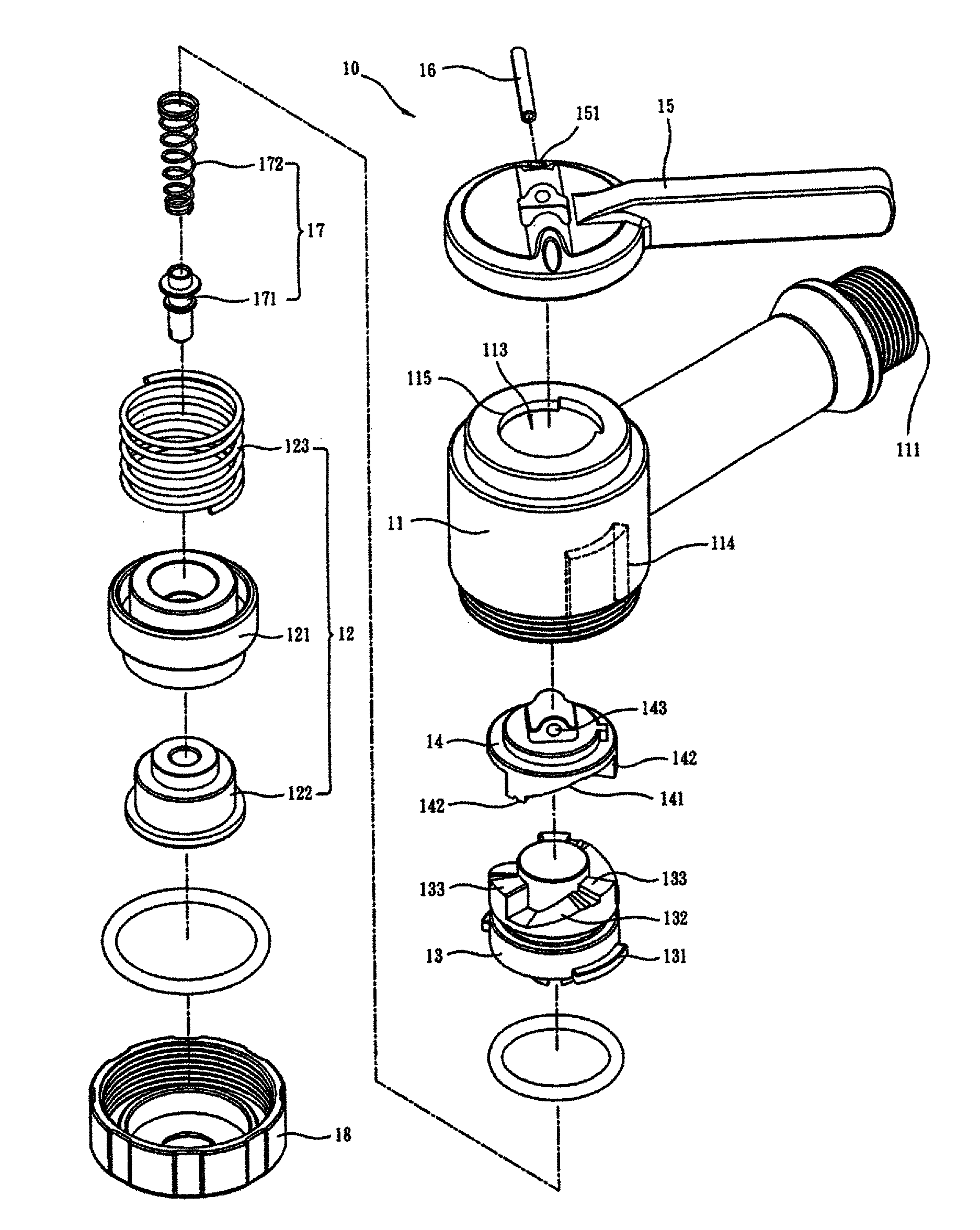
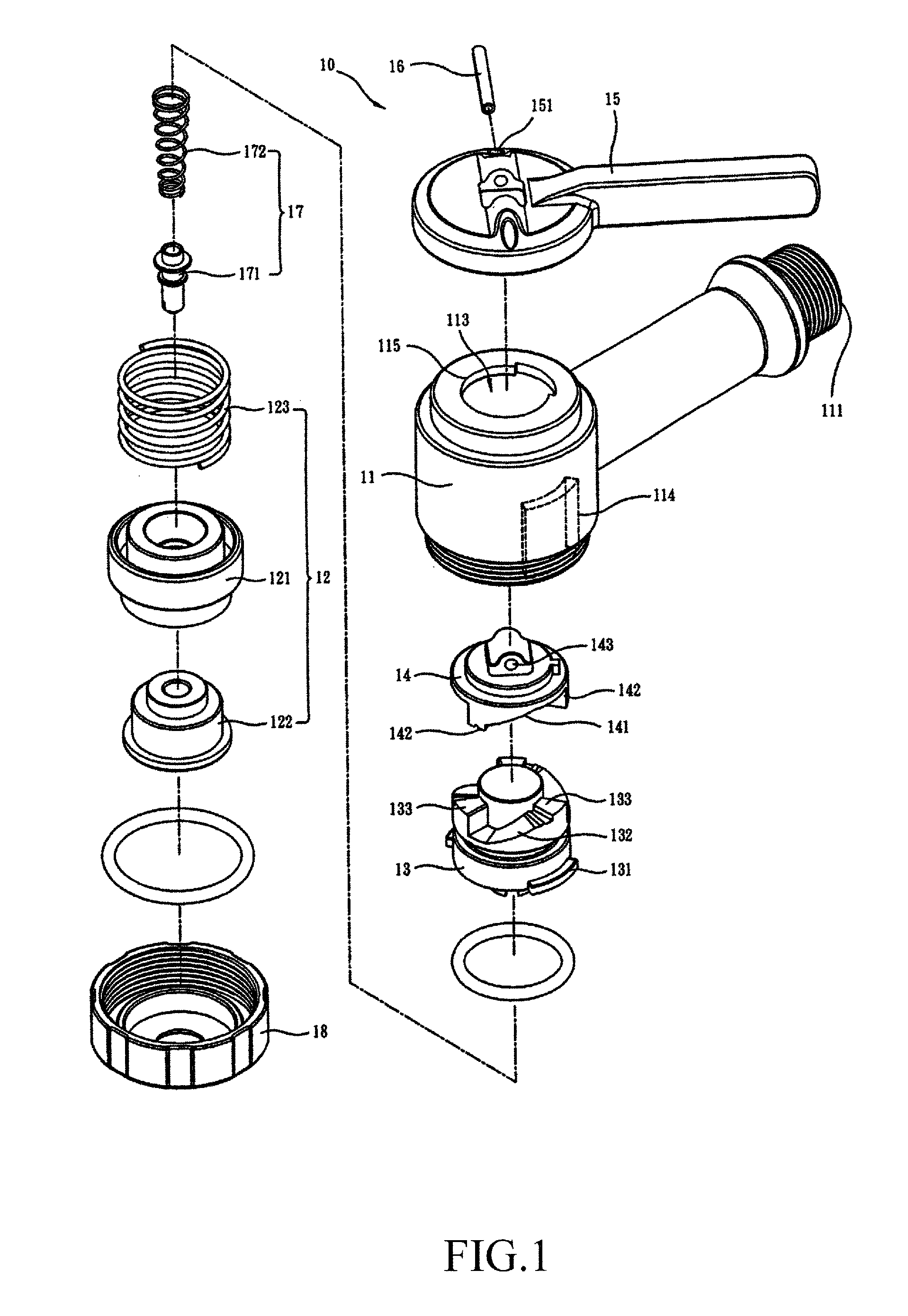
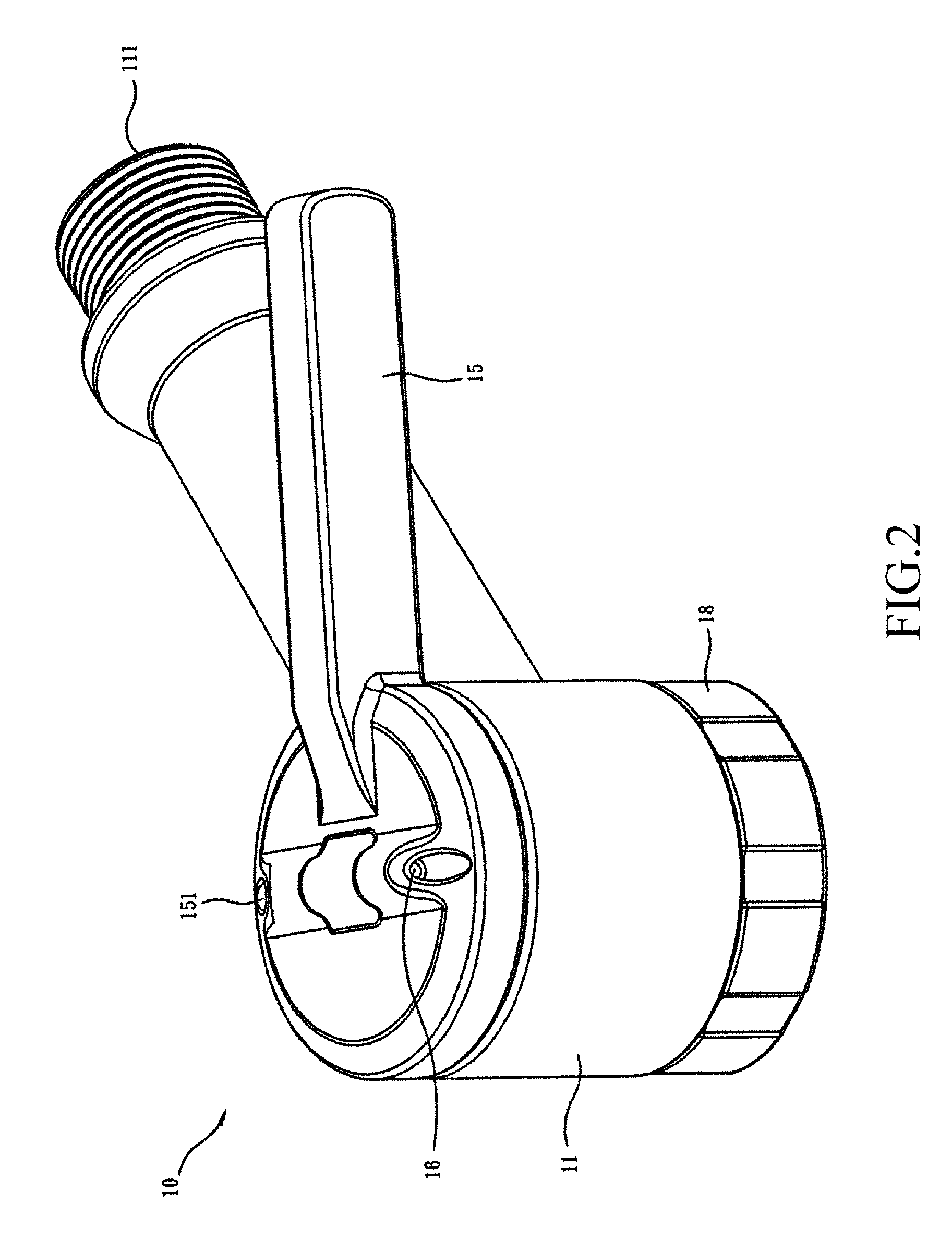
[0019]Referring to FIGS. 1-4, a horizontally-triggerable inflation connector constructed in accordance with a first preferred embodiment of the present invention, generally designated at 10, is shown, comprising a casing 11, a packing unit 12, a conversion member 13, a driving member 14, a pull bar 15, a pin 16, a nozzle unit 17, and a locking cap 18.

[0020]Referring to FIGS. 1-3, the casing 11 forms an air supply device connection port 111 in communication with the outside, an inflation connection p...


PUM


Abstract

A horizontally-triggerable inflation connector includes a casing, a packing unit, and a pull bar. The packing unit is received in the casing. The pull bar is arranged outside the casing and coupled to the packing unit. The pull bar is horizontally and reciprocally movable between a released position and a secured position. When the pull bar is at the released position, the packing unit is set in a released condition and when the pull bar is at the secured position, the packing unit is set in a compressed condition. Thus, the horizontally-triggerable inflation connector is operable to selectively secure or release an air valve so as to achieve convenience of operation.

Description

TECHNICAL FIELD OF THE INVENTION[0001]The present invention generally relates to an inflation connector, and more particularly to a horizontally-triggerable inflation connector.DESCRIPTION OF THE PRIOR ART[0002]An inflation device, such as manually-operating or electrically-operating air pumps, is provided with an inflation connector for connection with a valve of for example a tire in order to guide air from the inflation device through the valve of the tire for inflating the tire.[0003]After the tire valve is fit into the inflation connector, a trigger bar coupled to the inflation connector must be pulled to have the inflation connector securely coupled to the valve of the tire in order to prevent air leaking during the process of inflation.[0004]The conventional arrangement of the pull bar of the inflation connector is operated in such a way that the pull bar must be pulled upward from a horizontal position to a vertical position or pushed downward from the vertical position back...

Claims


Application Information

Patent Timeline
Patent Type & Authority Patents(United States)
IPC IPC(8): F16K15/20B60C23/10B60C29/06B60S5/04
CPCF16K15/20B60C23/10B60C29/06B60S5/04F04B33/005Y10T137/3724Y10T137/3584
Inventor WANG, LOPIN
Owner BETO ENG & MARKETING
Why Eureka
Try Eureka