Vehicle front structure

a front structure and vehicle technology, applied in the direction of roofs, vehicle cleaning, vehicle maintenance, etc., can solve the problems of plastic deformation and collision energy absorbed, and achieve the effect of satisfying impact absorption

Active Publication Date: 2015-05-19
HONDA MOTOR CO LTD
View PDF18 Cites 13 Cited by
  • Summary
  • Abstract
  • Description
  • Claims
  • Application Information

AI Technical Summary

Benefits of technology

[0030]The invention can provide a vehicle front structure which is capable of achieving satisfactory impact absorption.

Problems solved by technology

This causes plastic deformation in the suspension tower bar along the axial direction thereof and collision energy is absorbed.

Method used


Image

  • Vehicle front structure
  • Vehicle front structure
  • Vehicle front structure

Examples


first embodiment

[0053]the invention will be explained in detail with reference to FIGS. 1 to 10. In the explanations, a same element is labeled with a same numeral and redundant explanations will be omitted.

[0054]Further, in the explanations, when a direction is indicated, front-back, right-left, and up-down directions of a vehicle V will be used as references. A “vehicle width direction” and a “right and left direction” have a same meaning.

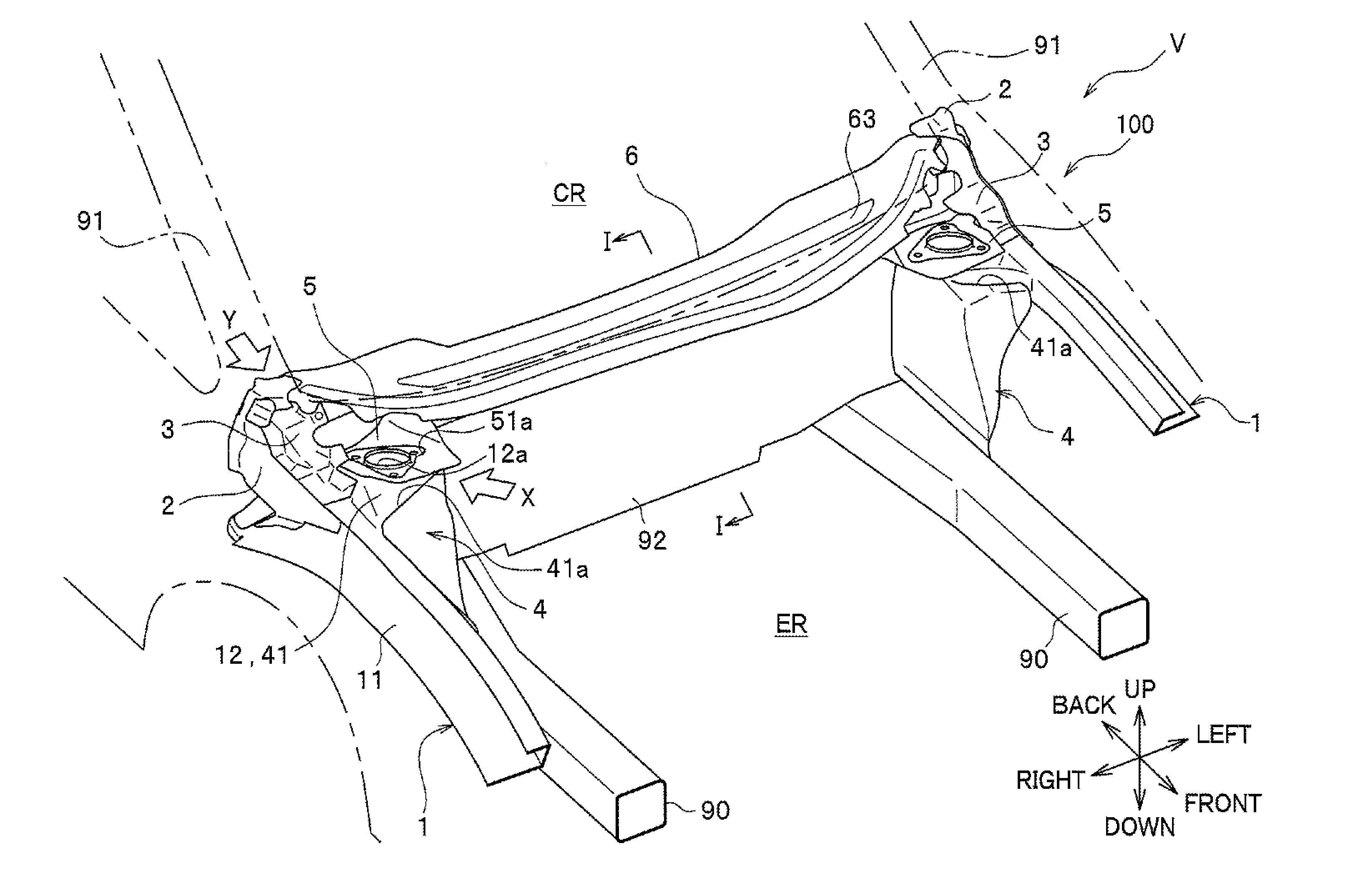
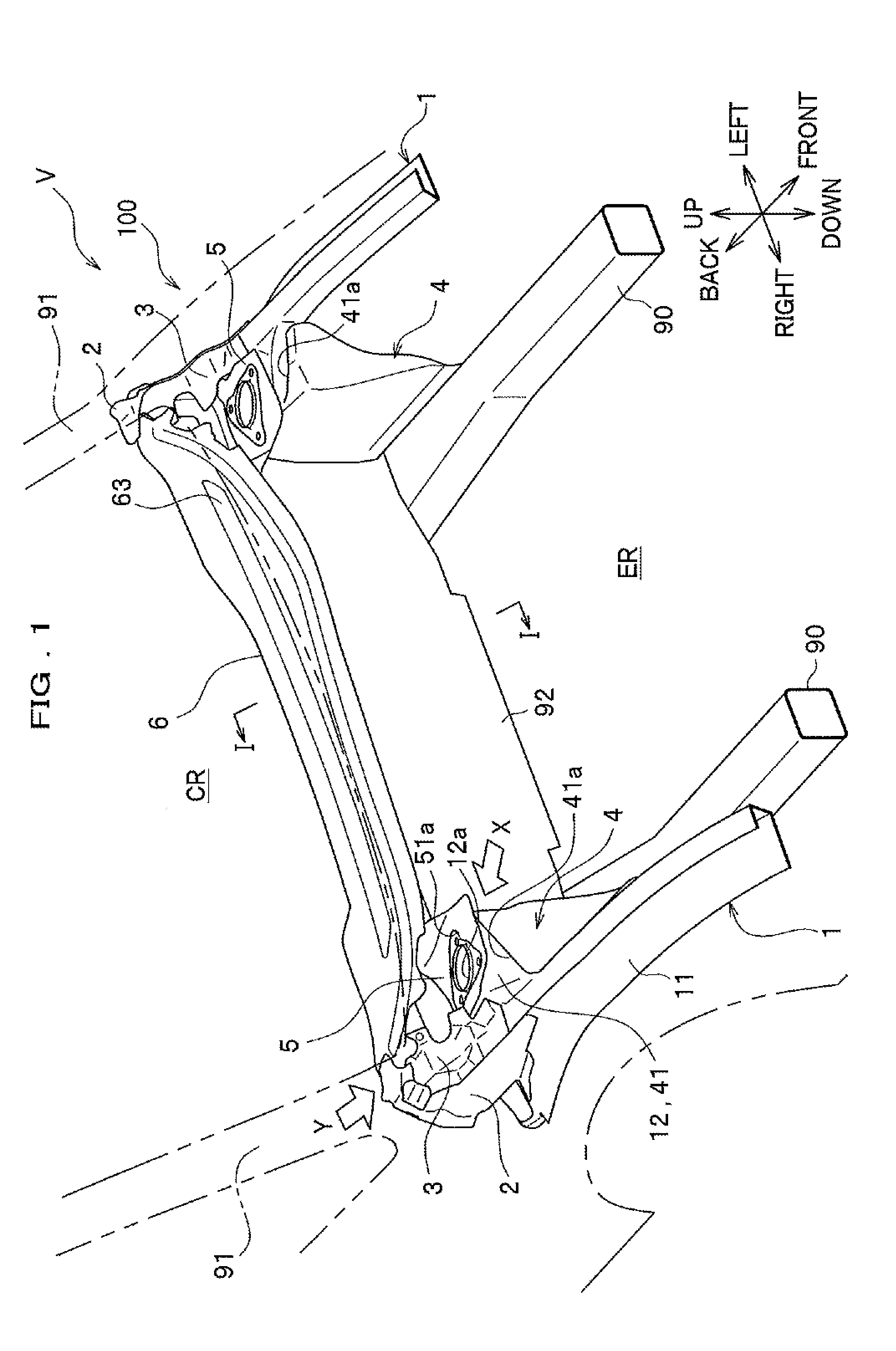
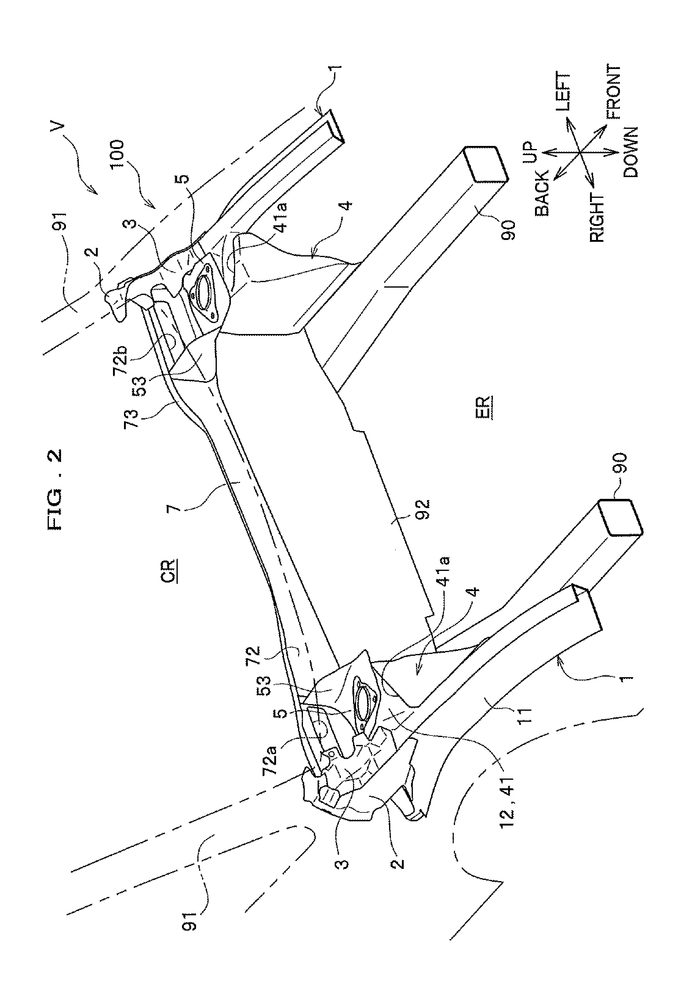
[0055]As illustrated in FIGS. 1 to 3, a vehicle front structure 100 according to the first embodiment of the invention mainly has upper members 1, 1, side extensions 2, 2, side members 3, 3, damper housings 4, 4, damper housing supports 5, 5, a windshield lower 6, a cross member 7 (see FIG. 2), and a cowl top 8 (see FIG. 3).

[0056]

[0057]As illustrated in FIG. 1, the upper member 1 is a steel member which is arranged at both right and left sides of the vehicle V and extends along the front-back direction. The upper member 1 has an approximately U-shaped main body ...

second embodiment

[0116]FIG. 12 is a partial plan view of the vehicle front structure according to the invention, and FIG. 16 is an end view along V-V line in FIG. 12.

[0117]As illustrated in FIG. 16, the side wall section 52 is a section which extends downward and backward from the rear end part of the damper housing fixed section 51. The side wall section 52 positions behind the rear end part at an upper side of the damper housing 4 and extends along the rear end part. The side wall section 52 has the slope section (front wall section) 52a extending incliningly so as to position downward as extending backward from the rear end part of the damper housing fixed port 51, and the bottom wall section 52b extending backward from the lower end part of the slope section 52a and fixed on the cross member 7. The bottom wall section 52b inclines to position downward as extending outside in the vehicle width direction.

[0118]As illustrated in FIG. 13, the vertical wall section 53 is a linear section which extend...


PUM


Abstract

The vehicle front structure 100 has a windshield lower 6, a cross member 7 fixed on the windshield lower 6, an upper member 1 extending in a front-back direction of a vehicle, a damper housing 4 fixed inside the upper member 1 in a vehicle width direction and arranged in front the cross member 7, and a damper housing support 5 coupling the cross member 7 with the damper housing 4. A closed section K is formed by the windshield lower 6 and the cross member 7. The damper housing support 5 has a damper housing fixed section 51 which is fixed on an upper surface 41 of the damper housing 4 and a vertical wall section 53 which extends backward from an inside of the damper housing fixed section 51 in the vehicle width direction and is fixed on the cross member 7.

Description

TECHNICAL FIELD[0001]The invention relates to a vehicle front structure.BACKGROUND ART[0002]Conventionally, a vehicle front structure has been known in which a collision load generated at a time of front collision is transmitted dispersively.[0003]For example, Patent Literature 1 discloses providing first members between a right and left pair of front side frames extending in a front-back direction of a vehicle and front end parts of a right and left pair of suspension towers arranged outside the front side frames respectively, and transmitting a collision load applied on the front side frames to the suspension towers dispersively via the first members. Patent Literature 1 further discloses providing second members between rear end parts of the suspension towers and a front end part of a cowl box supporting a lower end part of a windshield respectively, and transmitting the collision load transmitted to the suspension towers to the cowl box via the second members.[0004]Still further...

Claims


Application Information

Patent Timeline
Patent Type & Authority Patents(United States)
IPC IPC(8): B62D25/08
CPCB62D25/081B62D25/08B62D25/082B62D25/088
Inventor SASAKI, KAZUTADANIHEI, HIDEFUMINAOI, DAISUKEEGUCHI, MASANOBU
Owner HONDA MOTOR CO LTD
Why Eureka
Try Eureka