
Front body structure of vehicle

Inactive Publication Date: 2006-06-01
TOYOTA JIDOSHA KK
View PDF13 Cites 18 Cited by
  • Summary
  • Abstract
  • Description
  • Claims
  • Application Information

AI Technical Summary

Benefits of technology

[0005] In view of the above facts, an object of the present invention is to obtain a front body structure of a vehicle, in which satisfactory impact absorption can be achieved both at the time of offset collision and at the time of full-lapped collision.
[0008] On the other hand, when the vehicle comes into offset collision, the state in which the collided front side member is fixed to the connecting member is maintained by the fixing mechanism disposed at the rear fixing portions of the collided front side member and the connecting member. As a result, the collided front side member receives a part of the load and is deformed so that the impact can be absorbed, and the fixing mechanism also receives a part of the load and is deformed so that the impact can be absorbed. Further, the other front side member also receives a part of the load via the fixing mechanism and is deformed so that the impact can be absorbed.
[0009] As a result, even in the case of offset collision, substantially the same impact absorption effect as in the case of full-lapped collision can be obtained, and satisfactory impact absorption can be thus achieved both at the time of offset collision and at the time of full-lapped collision.
[0011] Accordingly, since the front suspension member can be used as the connecting member, there is no need to provide a particular connecting member and the structure is thus simplified.

Problems solved by technology

However, in the structure of JP-A No. 11-171046, even when the vehicle comes into offset collision, the right and left bolts on the rear side slip from the rear-end openings of the slits, and the impact is absorbed only by the collided front side member.
Therefore, the amount of impact absorption in the case of offset collision is less than that in the case of full-lapped collision (full collision), and satisfactory impact absorption cannot be achieved.
Further, in the structure of JP-A No. 11-198854, the satisfactory impact absorption is limited by the problem of strength of the compass mechanism against a large collision load.

Method used


Image

  • Front body structure of vehicle
  • Front body structure of vehicle
  • Front body structure of vehicle

Examples


Embodiment Construction

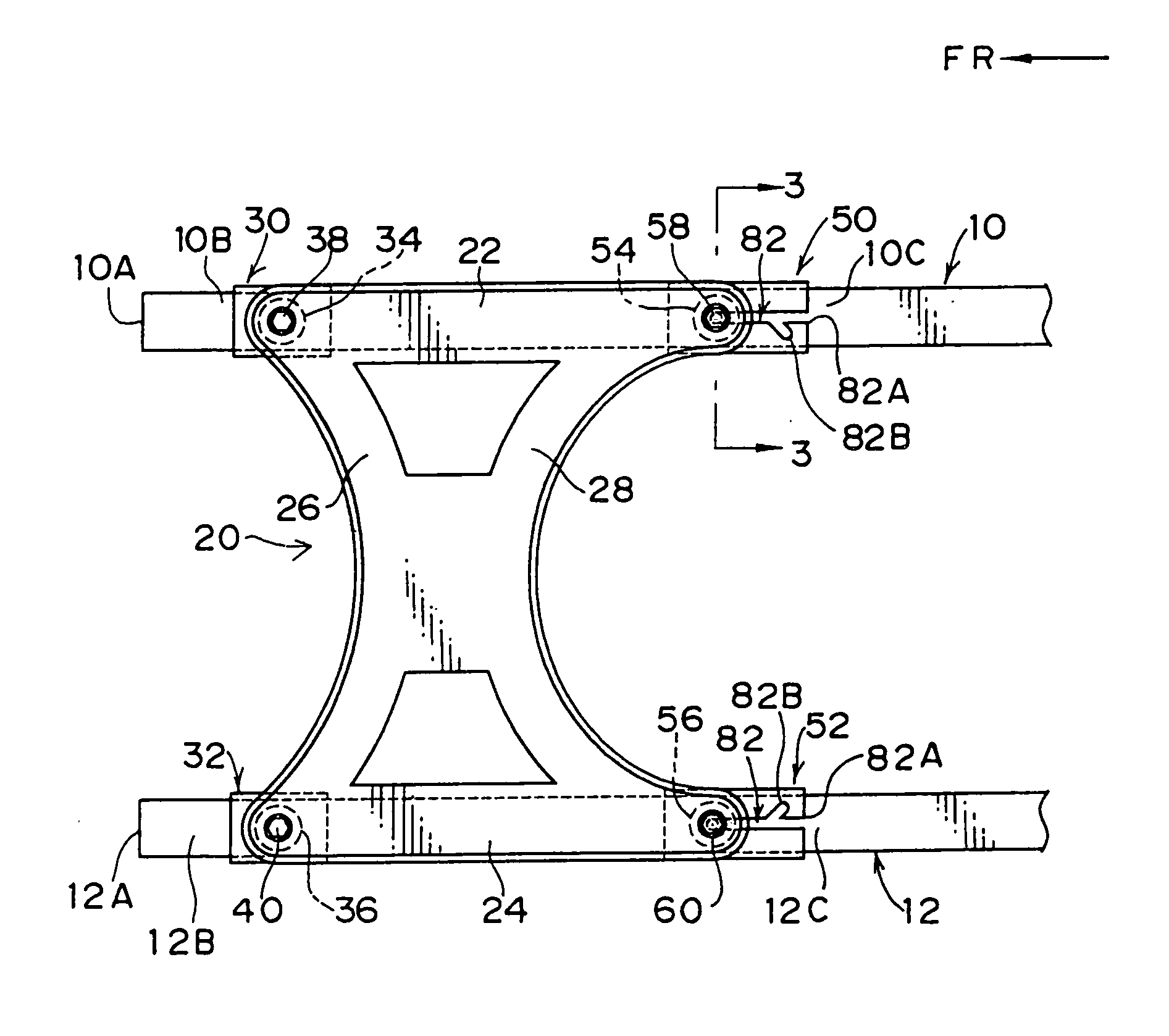
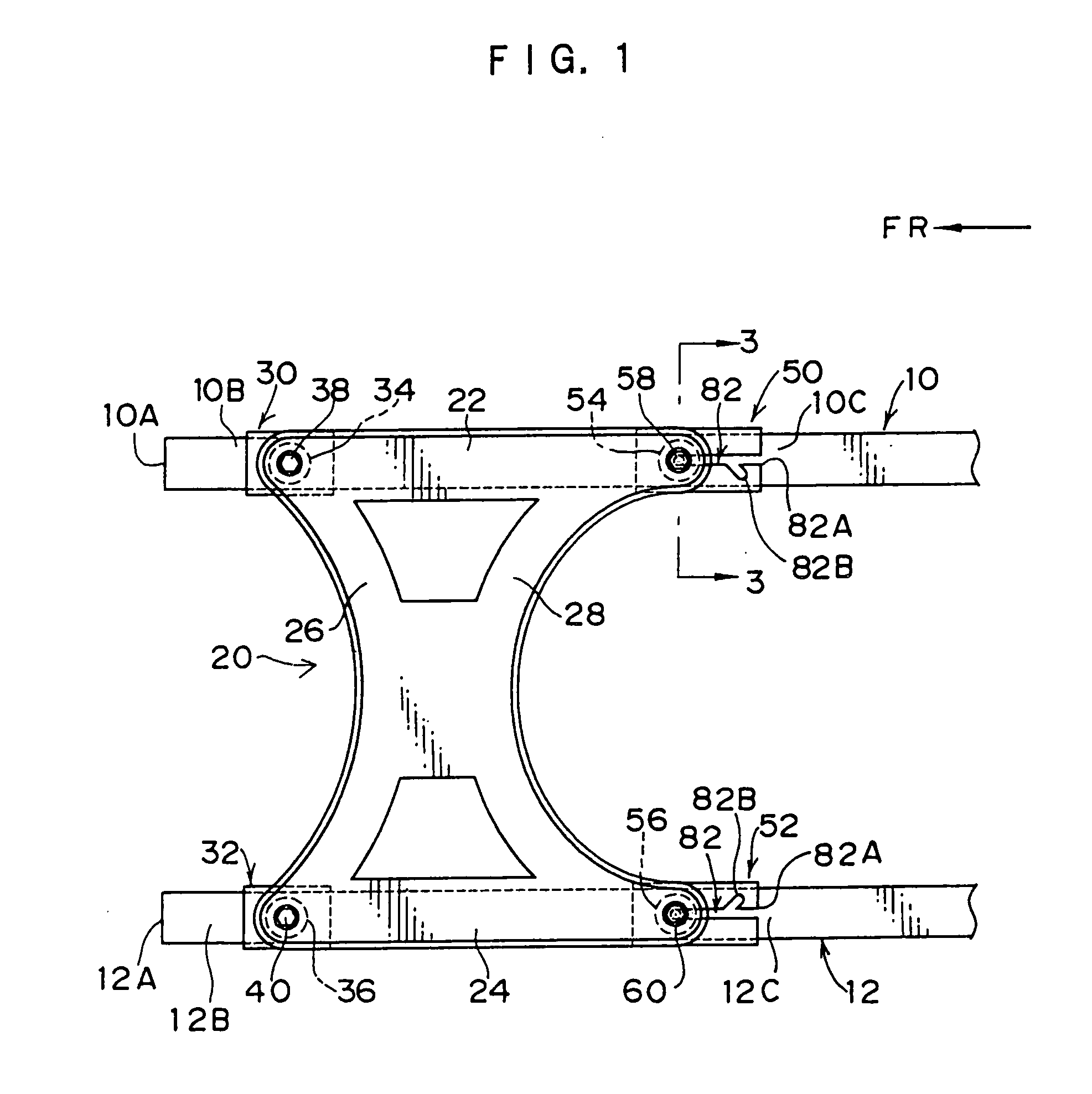
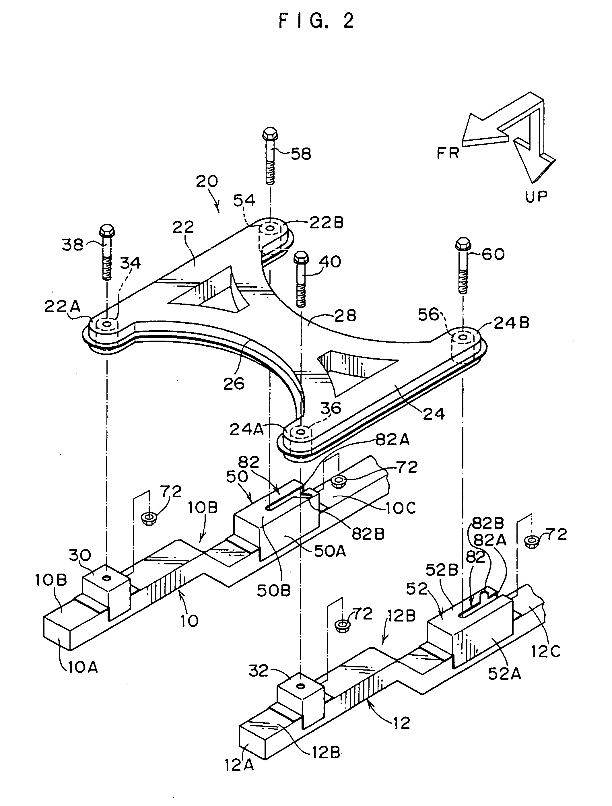
[0022] An embodiment of a front body structure of a vehicle according to the present invention will be described with reference to FIGS. 1 to 8.

[0023] In these figures, Arrows FR indicate the front direction of the vehicle, and Arrows UP indicate the upper direction thereof.

[0024] As shown in FIG. 1, in this embodiment, a pair of right and left front side members 10, 12 are disposed at a front portion of a vehicle body along the longitudinal direction thereof. A front bumper (not shown) is suspended between front ends 10A, 12A of the front side members 10, 12. Further, a front suspension member 20 serving as a connecting member is suspended between front portions of the pair of right and left front side members 10, 12.

[0025] As shown in FIG. 2, the front suspension member 20 is structured such that a front cross member 26 and a rear cross member 28 are suspended between two linear side rails 22, 24 extending along the longitudinal direction of the vehicle. The front cross member ...


PUM


Abstract

In a front body structure of a vehicle according to the present invention, satisfactory impact absorption can be achieved both at the time of offset collision and at the time of full-lapped collision. When a load applied to an offset-collided front side member (10 or 12) from a front side of the vehicle is equal to or more than a predetermined value, the collided front side member (10 or 12) is deformed. Thus, a front suspension member (20) rotates. As a result, a bolt (58) passing through the front suspension member (20) fits into a branch (82B) of a slit (82) of a rear mounting bracket (50 or 52) disposed on the collided front side member (10 or 12), and the state in which the collided front side member (10 or 12) is fixed to the front suspension member (20) is maintained.

Description

TECHNICAL FIELD [0001] The present invention relates to a front body structure of a vehicle, and specifically to a front body structure of a vehicle for reducing the impact acting on occupants at the time when the vehicle such as an automobile comes into frontal collision. BACKGROUND ART [0002] Conventionally, in a front body structure of a vehicle for reducing the impact acting on occupants at the time when the vehicle such as an automobile comes into frontal collision, a front sub-frame is supported by bolts to brackets which are fixed to a main frame and in which rear-end opening slits are formed, and the bolts on the rear side slip from the rear-end openings of the slits at the time of frontal collision. Accordingly, the main frame can be crushed without the interruption of the front sub-frame. This structure is disclosed in, for example, Japanese Patent Application Laid-Open (JP-A) No. 11-171046. [0003] Further, in another front body structure of a vehicle for reducing the impa...

Claims


Application Information

Patent Timeline
IPC IPC(8): B62D21/15B60R27/00B60R21/02B60R99/00B62D25/20B62D21/00B62D21/02B62D21/12
CPCB62D21/155
Inventor KISHIMA, FUMIHIKO
Owner TOYOTA JIDOSHA KK
Learn More