Vehicle seat

a seat and vehicle technology, applied in the field of seats, can solve the problems of increasing manufacturing costs and increasing weight of the seat, and achieve the effect of enhancing strength and reducing the moment of the lock uni

Active Publication Date: 2015-05-19
ADIENT US LLC
View PDF28 Cites 4 Cited by
  • Summary
  • Abstract
  • Description
  • Claims
  • Application Information

AI Technical Summary

Benefits of technology

[0005]According to this related technique, as a structure to support the seat on the floor, the two lock means are operated in conjunction with each other so as to securely lock the seat. However, in the case where seatbelts for three passengers are disposed, a seatbelt anchor load of 1.5 passengers may be applied to each of the lock means and the leg. If the strength of each of the lock means and the leg is to be enhanced to make them able to withstand such seatbelt anchor load, not only may their weights be increased but also their manufacturing costs may be increased.
[0006]An object of the present invention is to provide a vehicle seat with a seatbelt anchor having improved strength without increasing the manufacturing costs of lock means and a leg.SOLUTION TO PROBLEM
[0008]According to the above aspect, the first lower end portion of the belt anchor bracket is supported on the lock unit rotatably in the front-rear direction; the second lower end portion of the belt anchor bracket is fixed to the leg; and the seatbelt anchor is supported on the upper end portion of the belt anchor bracket rotatably in the front-rear direction. Thus, in a normal state where no load is applied to the seatbelt anchor, the leg holds the seat cushion substantially horizontally. In a sudden braking state where load is applied to the seatbelt anchor, the belt anchor bracket is deformed, so that the upper end portion of the belt anchor bracket supporting the seatbelt anchor is moved toward the front side. By the deformation of the belt anchor bracket, the impact energy can be absorbed. Moreover, a point on the belt anchor bracket to the seatbelt anchor is moved toward the front side, so that the moment of the lock unit is reduced. Accordingly, the strength of the seatbelt anchor can be increased without increasing the manufacturing cost of the leg.
[0010]According to the above configuration, the metal linking bracket Is provided bridging between the upper end portion of the belt anchor bracket and the first lower end portion of the belt anchor bracket. Accordingly, the strength of the belt anchor bracket can be enhanced greatly.
[0012]According to the above configuration, of the front lock unit and the rear lock unit separated from each other in the front-rear direction, the rear lock unit has the first lower end portion of the belt anchor bracket supported thereon rotatably in the front-rear direction. Thus, load applied to the seatbelt anchor in sudden braking or the like is transmitted to the rear lock unit. As a result, the moment of the lock unit is reduced. Accordingly, the leg, the rear Lock unit, and the engagement member do not need to greatly enhance their strength.

Problems solved by technology

If the strength of each of the lock means and the leg is to be enhanced to make them able to withstand such seatbelt anchor load, not only may their weights be increased but also their manufacturing costs may be increased.

Method used


Image

  • Vehicle seat
  • Vehicle seat
  • Vehicle seat

Examples


Embodiment Construction

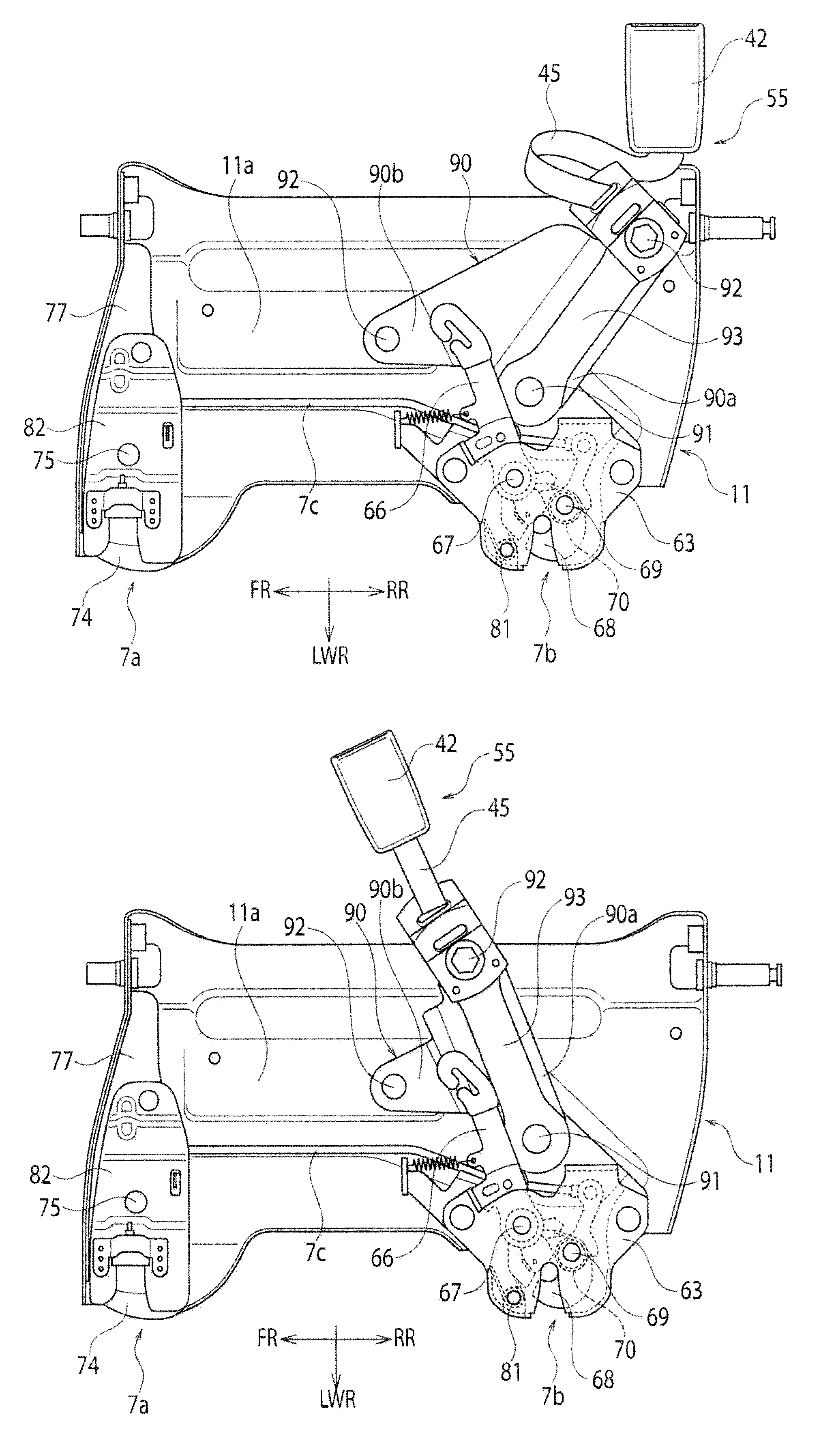
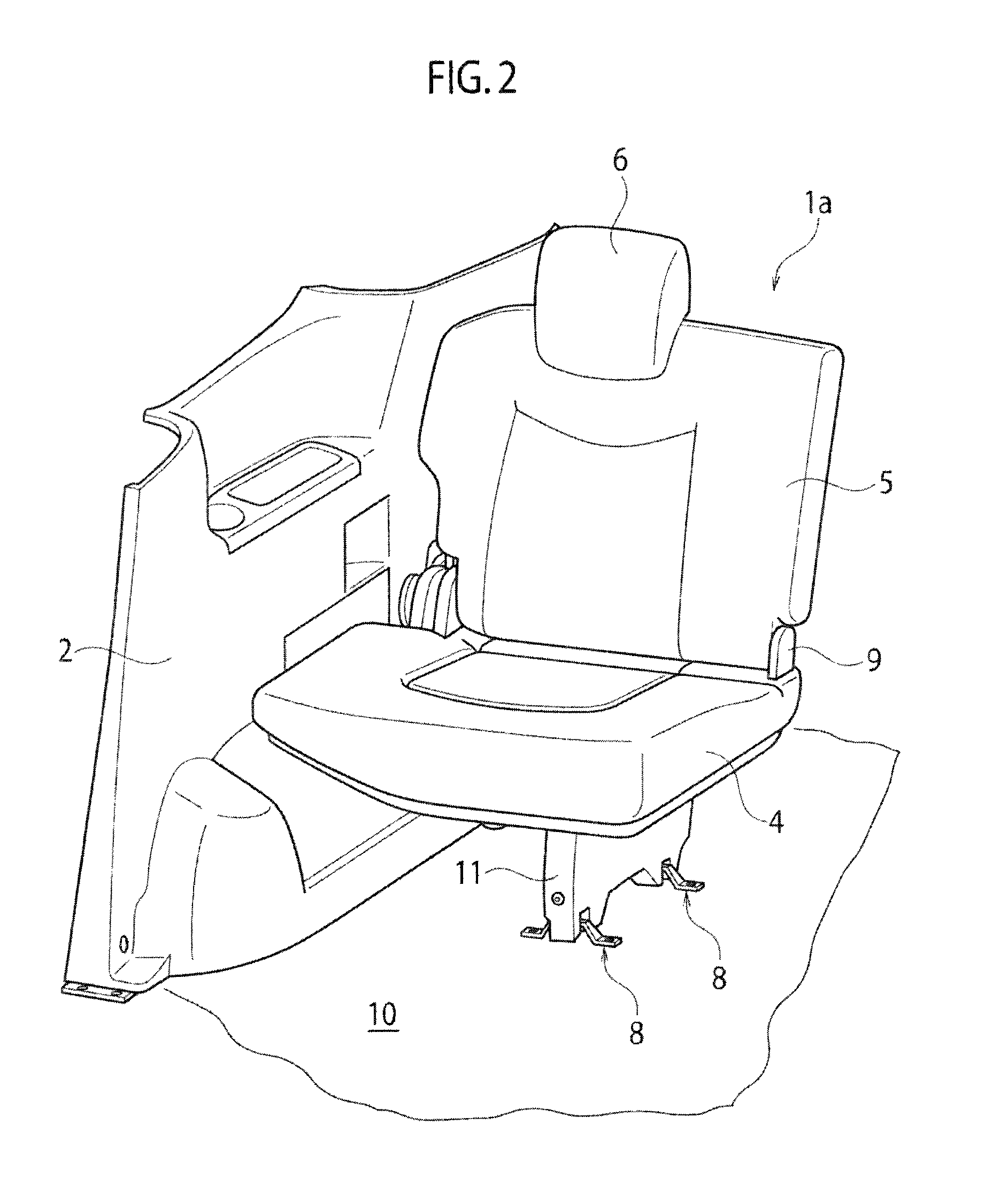
[0020]The object of providing a vehicle seat with a seatbelt anchor having improved strength without increasing the manufacturing costs of lock units and a leg is achieved by including: a seat cushion having one side supported on a side panel of a vehicle rotatably in a left-right direction of the vehicle; a leg hanging downward from the other side of the seat cushion and being capable of horizontally holding the seat cushion on a floor panel of the vehicle; a lock unit engageable with and disengageable from an engagement member provided to the floor panel; and a belt anchor bracket having a first lower end portion supported on the lock unit rotatably in a front-rear direction of the vehicle, a second lower end portion fixed to the leg, and an upper end portion supporting a seatbelt anchor rotatably in the front-rear direction.

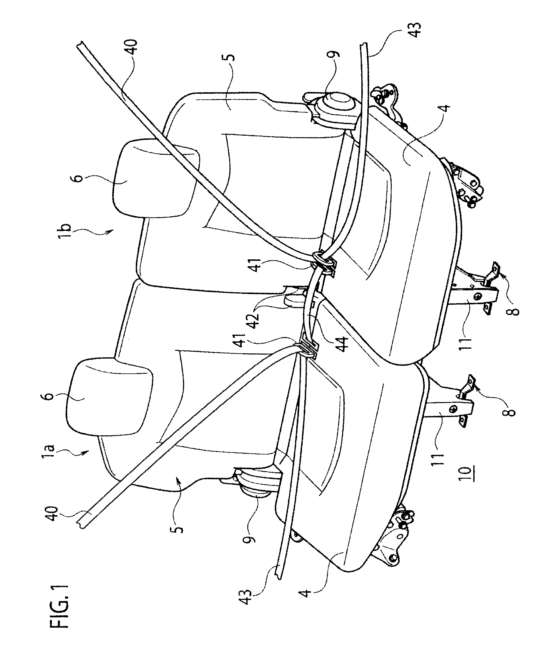
[0021]Hereinbelow, an embodiment of the present invention will be described in detail with reference to FIGS. 1 to 7.

[0022]FIG. 1 shows seats 1a, 1b mounted o...


PUM


Abstract

One lower end portion of a belt anchor bracket is supported on a lock unit rotatably in a front-rear direction, the other lower end portion of the belt anchor bracket is fixed to a leg, and a seatbelt anchor is supported on an upper end portion of the belt anchor bracket rotatably in the front-rear direction.

Description

CROSS REFERENCE TO RELATED APPLICATIONS[0001]The present application is a National Stage of International Application No. PCT / JP2010 / 070763 filed on Nov. 22, 2010, the entire disclosure of which is incorporated herein by reference.TECHNICAL FIELD[0002]The present invention relates to a seat for a vehicle such as an automobile.BACKGROUND ART[0003]As a related vehicle seat, there is a seat designed such that a lateral part of the seat on a vehicle body side is supported by a hinge mechanism so as to be rotatable between a position at which the seat is raised and a position at which one can sit thereon, and a lock device is provided to a leg of the seat given on the opposite side thereof from the vehicle body, i.e. the cabin side (see Patent Literature 1) . The lock device is formed of front lock means and rear lock means which are capable of engaging with front and rear engagement members fixed to a floor panel. While the rear lock means is in an engaged state, the front lock means is...

Claims


Application Information

Patent Timeline
Patent Type & Authority Patents(United States)
IPC IPC(8): B60R22/00B60N2/30B60N2/015B60N2/68B60R22/26B60R22/02B60N2/90
CPCB60R22/26B60N2/3043B60R2022/021B60N2/3011B60N2/01583B60N2/688
Inventor MIYAZAWA, MASAAKIKONDO, IKUO
Owner ADIENT US LLC
Why Eureka
Try Eureka