
Suspension device for outboard motor, vessel propulsion apparatus, and vessel

a suspension device and outboard motor technology, applied in the direction of outboard propulsion units, marine propulsion, vessel construction, etc., can solve the problems of inability to prevent electrolytic corrosion of trim rods, inability to use outboard motors to prevent electrolytic corrosion, etc., to achieve the effect of effectively preventing electrolytic corrosion and changing the structure of the suspension devi

Inactive Publication Date: 2015-05-19
YAMAHA MOTOR CO LTD
View PDF3 Cites 4 Cited by
  • Summary
  • Abstract
  • Description
  • Claims
  • Application Information

AI Technical Summary

Benefits of technology

The trim rod is reliably grounded during use, preventing electrolytic corrosion without significant modifications to the existing structure, ensuring continuous electrical conduction despite potential oxide films or foreign matter, thus extending the component's lifespan.

Problems solved by technology

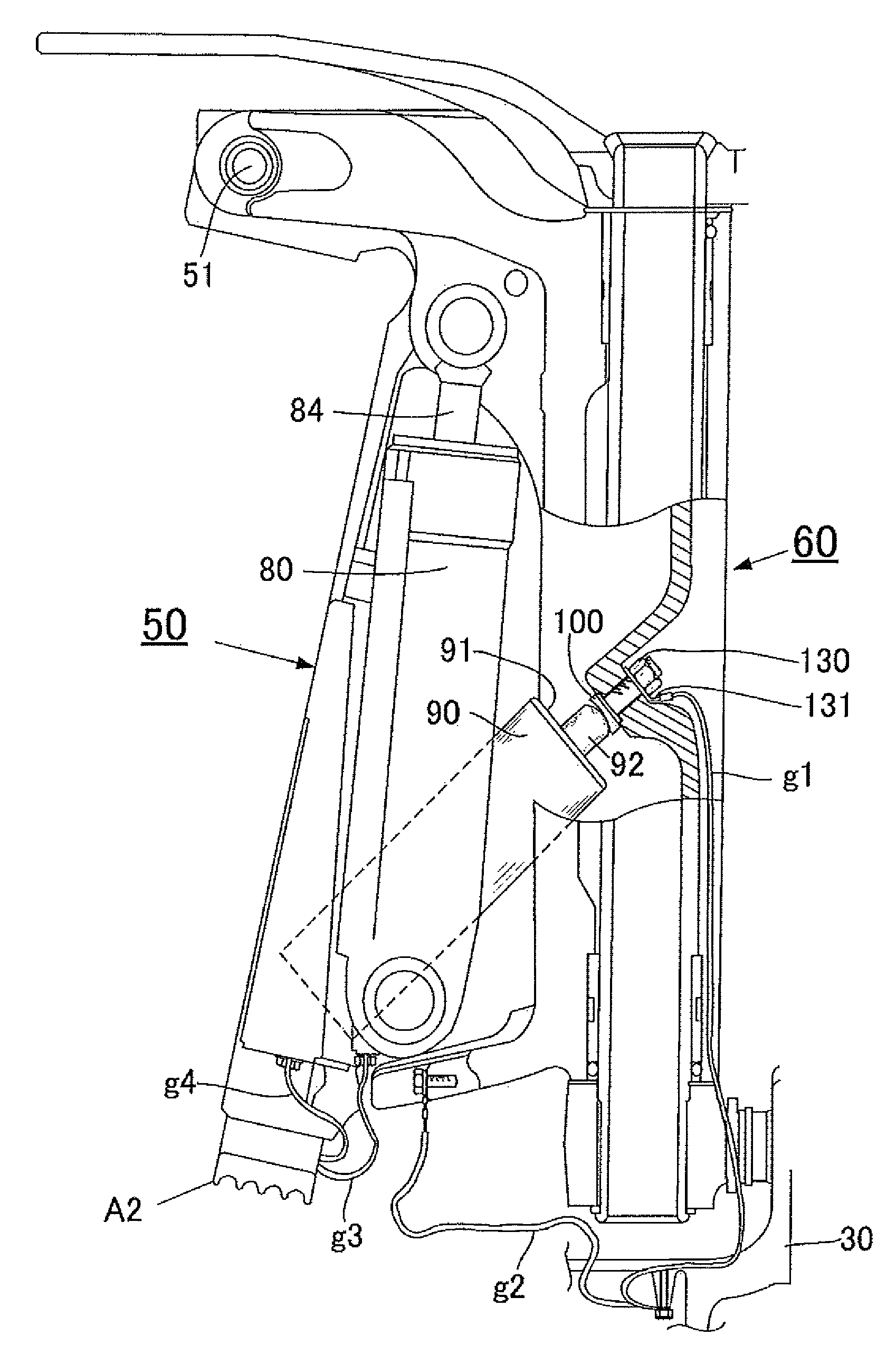
Therefore, even when the cylinder tube or trim rod guide of the trim cylinder is connected to the anode by a ground wire, a sacrificial corrosion preventing effect by the anode does not reach the trim rod.
The trim rod may therefore be electrolytically corroded.
In either case, the trim rod electrolytically corrodes due to a metal material having a large ionization tendency being ionized and eluted into seawater.
However, during use of the outboard motor, there is little time that the trim rod is in a state of maximum projection and, thus, the trim rod is most often in a state of not being electrically connected with the rod guide.
Thus, with the structure above, the effect to prevent electrolytic corrosion of the trim rod cannot be expected during use of the outboard motor.
In particular, when the operating time of the outboard motor is long, the trim rod may be electrolytically corroded.
Thus, with the above structure, the effect to prevent electrolytic corrosion of the trim rod is not always expected.

Method used


Image

  • Suspension device for outboard motor, vessel propulsion apparatus, and vessel
  • Suspension device for outboard motor, vessel propulsion apparatus, and vessel
  • Suspension device for outboard motor, vessel propulsion apparatus, and vessel

Examples


Embodiment Construction

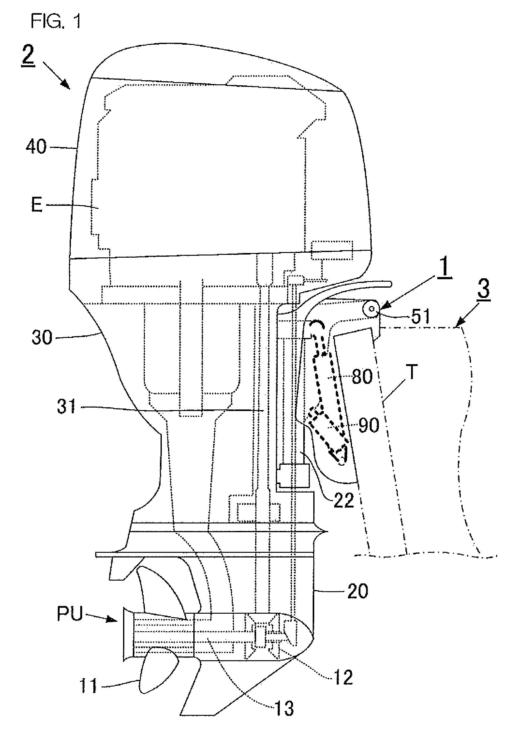
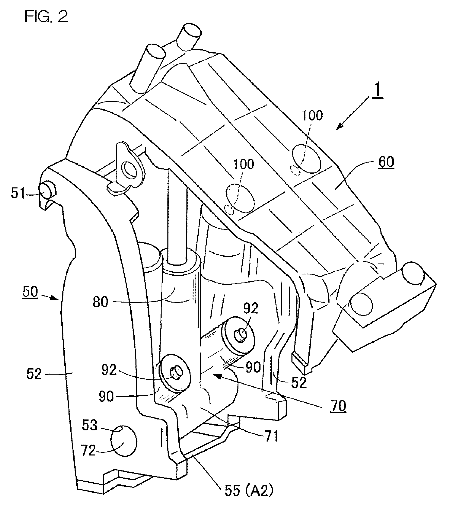
[0043]As shown in FIG. 1, a vessel includes a hull that floats on a water surface and a vessel propulsion apparatus that propels the hull. The vessel propulsion apparatus includes a suspension device 1 that is attachable to a rear portion (stern) of the hull and an outboard motor 2 that is attached to the hull via the suspension device 1.

[0044]As shown in FIG. 1, the outboard motor 2 includes a lower casing 20 disposed in a lower portion of the outboard motor 2. A propeller unit PU is held by the lower casing 20. The propeller unit PU includes a cylindrical propeller member including a plurality of blades 11 and a propeller damper D (refer to FIG. 9) housed in the propeller member. A forward / reverse switching mechanism 12 and a propeller shaft 13 are provided in the lower casing 20. An upper casing 30 is disposed on the lower casing 20, and fixed to the lower casing 20. The upper casing 30 houses a drive shaft 31 in a vertical orientation. An engine E is installed on the upper casin...


PUM


Abstract

A swivel bracket is coupled via a horizontal bracket to a clamp bracket to be mounted on a vessel. A trim mechanism adjusts a trim angle of an outboard motor by rotating the swivel bracket about the horizontal shaft. The trim mechanism includes a trim cylinder coupled to the clamp bracket and a trim rod that is projectable and retractable from the trim cylinder. A thrust receiver is attached to the swivel bracket. The thrust receiver receives a load from the trim rod. The thrust receiver is grounded. The thrust receiver includes a conducting portion in contact with the trim rod.

Description

BACKGROUND OF THE INVENTION[0001]1. Field of the Invention[0002]The present invention relates to a suspension device for an outboard motor, a vessel propulsion apparatus including the suspension device, and a vessel to be propelled by the vessel propulsion apparatus. In particular, the present invention relates to a suspension device for an outboard motor that prevents electrolytic corrosion of a trim rod that is extendable from a trim cylinder included in a trim angle adjusting device of an outboard motor, a vessel propulsion apparatus including the suspension device, and a vessel including the vessel propulsion apparatus.[0003]2. Description of the Related Art[0004]A suspension device to attach an outboard motor on a hull includes a clamp bracket, a swivel bracket tiltably coupled to the clamp bracket, and a tilt cylinder device interposed between both brackets.[0005]The clamp bracket removably fixes the suspension device to a stern of a vessel. An outboard motor is attached to th...

Claims


Application Information

Patent Timeline
Patent Type & Authority Patents(United States)
IPC IPC(8): B63H20/02B63H20/10
CPCB63H20/02B63H20/10
Inventor TAKASE, HIROAKI
Owner YAMAHA MOTOR CO LTD
Learn More