Projection display device comprising a light source

a technology of projection display and light source, which is applied in the direction of projection devices, television systems, instruments, etc., can solve the problems of shortening the life of the discharge lamp or flickering, and achieve the effect of keeping the noise of the entire device almost constan

Active Publication Date: 2015-05-26
SHARP NEC DISPLAY SOLUTIONS LTD
View PDF30 Cites 3 Cited by
  • Summary
  • Abstract
  • Description
  • Claims
  • Application Information

AI Technical Summary

Benefits of technology

[0012]According to the present invention, even when the number of revolutions of the fan for cooling the light source is changed at high speed in response to the output change of the light source, the noise of the entire device is kept almost constant.

Problems solved by technology

In particular, when the temperature of a luminous tube becomes equal to or more than a predetermined temperature, the life of the discharge lamp may be shortened or flickers may occur.

Method used


Image

  • Projection display device comprising a light source
  • Projection display device comprising a light source
  • Projection display device comprising a light source

Examples


first embodiment

[0033](First Embodiment)

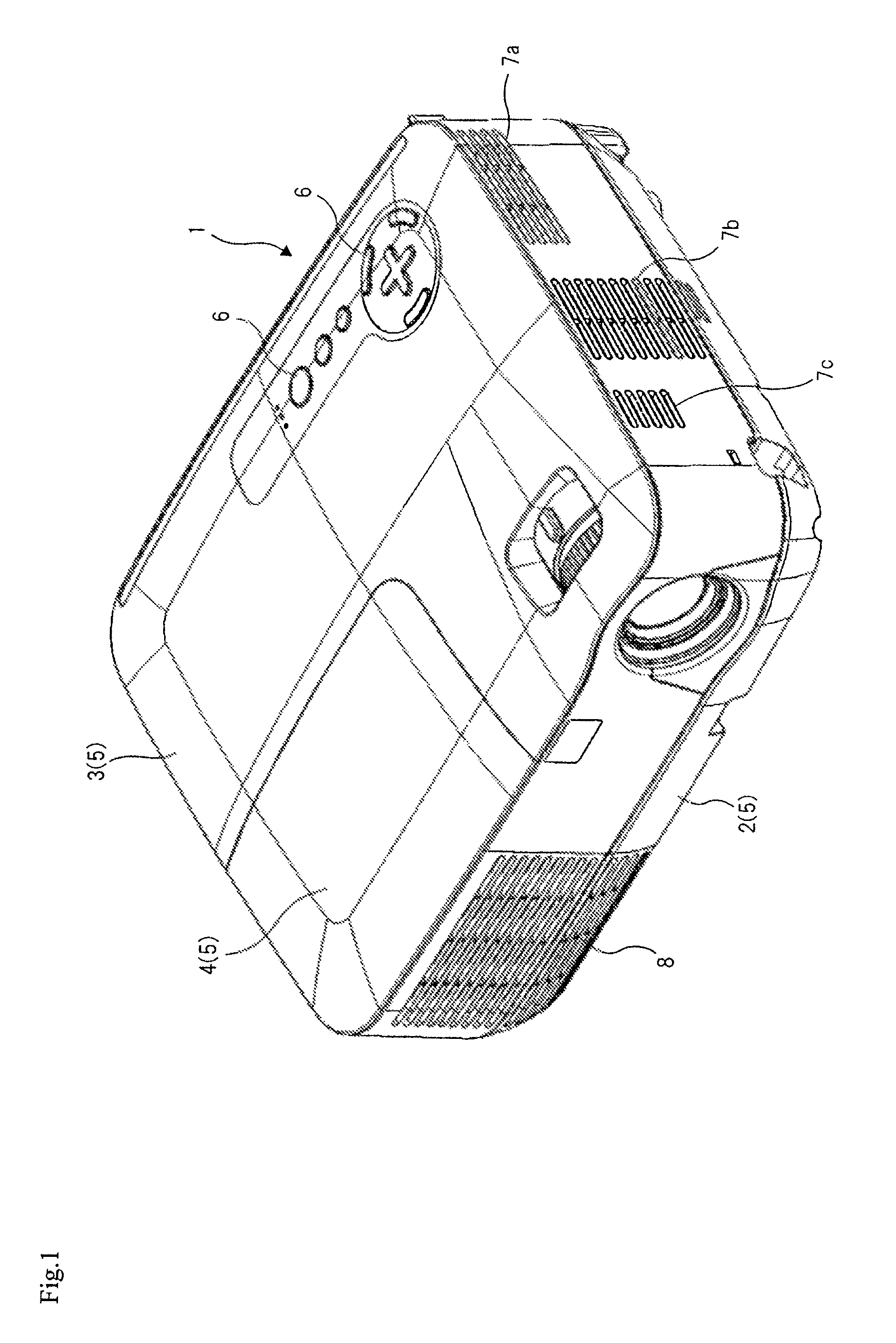
[0034]FIG. 1 is a perspective view showing the appearance of a projection display device according to the present invention. Projection display device 1 according to this embodiment has case 5 that includes bottom case 2, upper case 3, and lamp case 4. A plurality of control buttons 6 are formed on the surface of upper case 3. Three suction ports 7a to 7c are formed on the left surface of upper case 3 to introduce outside air into the case. Exhaust port 8 is formed on the front of upper case 3 to discharge air out of the case.

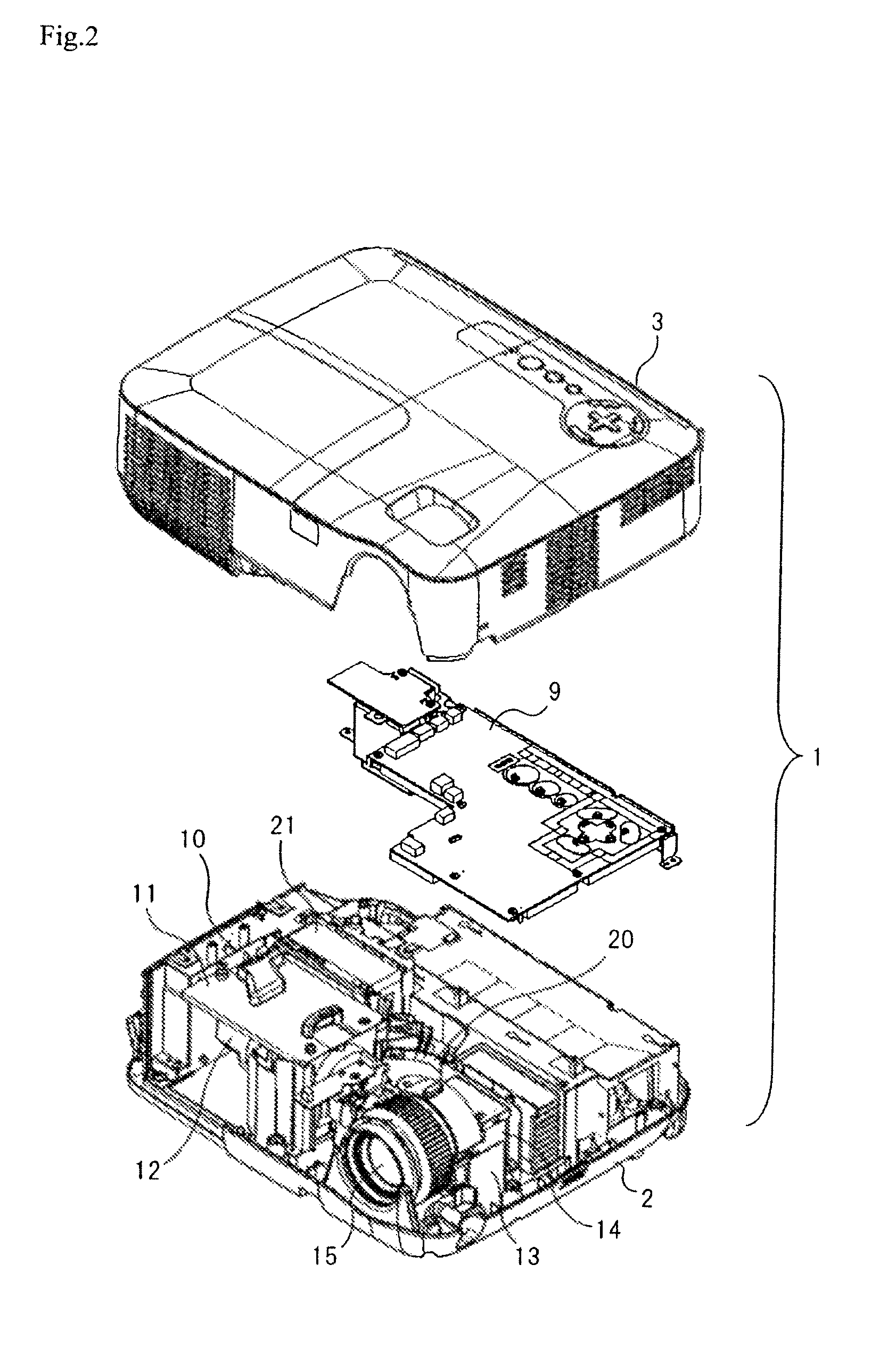
[0035]FIG. 2 is an exploded perspective view of projection display 1. FIG. 2 shows the removed state of upper case 3 and main substrate 9. A part of power supplied from the outside is supplied to lamp unit 11 via power source unit 10. The other part of the power supplied from the outside is supplied to main substrate 9 via power source unit 10. When a user presses a power source button, projection display device 1 is activated to light l...

second embodiment

[0049](Second Embodiment)

[0050]The basic configuration of a projection display device according to this embodiment is similar to that of the projection display device according to the first embodiment. The projection display device according to this embodiment includes a second sirocco fan (power source fan) for cooling a power source unit. The power source fan is a sirocco fan similar in shape and size to lamp fan 20.

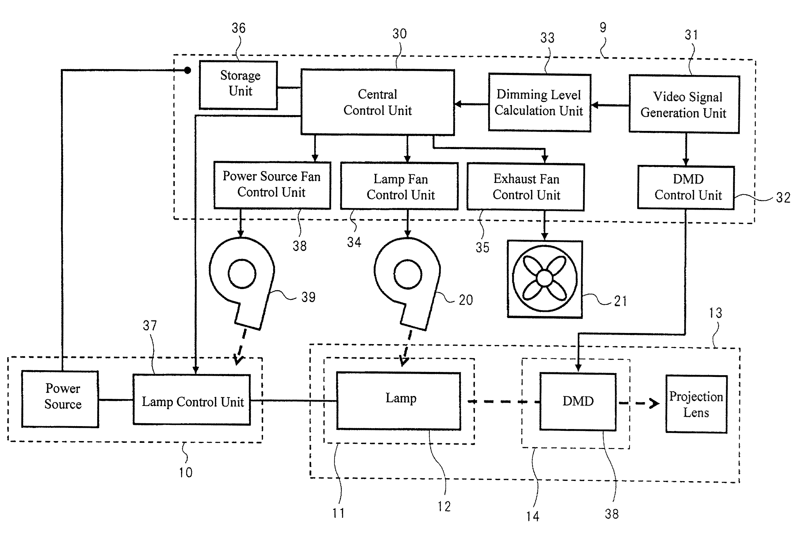
[0051]FIG. 10 is a control block diagram showing the projection display device according to this embodiment. Shown main substrate 9, power unit 10, and optical engine 13 are substantially similar to those of identical names shown in FIG. 5. Central control unit 30, video signal generation unit 31, DMD control unit 32, dimming level calculation unit 33, lamp fan control unit 34, exhaust fan control unit 35, storage unit 36, and lamp control unit 37 shown in FIG. 10 are substantially similar to those of identical names shown in FIG. 5. Further, lamp fan 20 and exhaust fa...


PUM


Abstract

A projection display device projects light modulated based on a video signal. The projection display device includes a light source, a first fan for cooling the light source, and a second fan different from the first fan. The number of revolutions of the first fan is increased or decreased with the increase or decrease of the output of the light source. The number of revolutions of the second fan is decreased when the number of revolutions of the first fan is increased, and increased when the number of revolutions of the first fan is decreased.

Description

TECHNICAL FIELD[0001]The present invention relates to a projection display device that includes a cooling fan for cooing a light source.BACKGROUND ART[0002]As the light source of the projection display device, a discharge lamp such as an ultra high pressure mercury lamp or a metal halide lamp is used. The temperature of the discharge lamp becomes very high during lighting. In particular, when the temperature of a luminous tube becomes equal to or more than a predetermined temperature, the life of the discharge lamp may be shortened or flickers may occur. Therefore, to maintain the temperature of the discharge lamp (luminous tube) within a predetermined range, the discharge lamp must be cooled.[0003]One of the known discharge lamp cooling methods is an air-cooling method that uses a cooling fan. According to the general air-cooling method, the number of revolutions of the cooling fan is controlled according to the increase or decrease of the output of the discharge lamp. Specifically...

Claims


Application Information

Patent Timeline
Patent Type & Authority Patents(United States)
IPC IPC(8): G03B21/16H04N5/74G09G3/34H04N9/31
CPCH04N9/3144G03B21/16H04N9/3155G09G3/3406
Inventor OKAZAWA, SHUNSUKEOKADA, TAKAYUKI
Owner SHARP NEC DISPLAY SOLUTIONS LTD
Why Eureka
Try Eureka