Vegetation cutting device

a cutting device and vegetable technology, applied in the field of vegetable cutting devices, can solve problems such as noise pollution

Active Publication Date: 2017-08-15
BLACK & DECKER INC
View PDF22 Cites 1 Cited by
  • Summary
  • Abstract
  • Description
  • Claims
  • Application Information

AI Technical Summary

Benefits of technology

[0015]When the vegetation cutting device is in trimming mode, a guard piece surrounding the cutting line may reflect noise into vegetation being cut and the vegetation will naturally will dampen the noise. In contrast when the vegetation cutting device is in edging mode the guard may reflect the noise into the open air. By determining which mode the cutting head is in, the speed of the motor can be adjusted accordingly. This means that the speed of the motor can be automatically increased when the cutting head is rotated into trimming mode and decreased when the cutting head is rotated into edging mode. This means that the difference in noise levels experienced by the user when the vegetation cutting device is used in trimming mode or in edging mode can be accommodated accordingly.
[0016]By reducing the speed of the cutting head in edging mode, the noise level is also reduced in edging mode. The vegetation cutting device can be designed to improve the cutting characteristics whilst keeping the noise below a desired threshold. For example the vegetation cutting device can have more powerful motor which has a greater maximum speed of the motor in trimming mode, but limits the maximum speed of the motor in edging mode in order to keep the noise generated within acceptable limits. Additionally or alternatively the dynamic speed control allows the vegetation cutting device to have a larger cutting swath which is rotated at a slower speed in edging mode.
[0017]The vegetation cutting device maximum motor speed is not limited by the noise level the user experiences in the orientation (e.g. edging mode) which generates the greatest level of noise. Instead the vegetation cutting device has a dynamic motor speed control which depends on the orientation of the cutting head. This provides a better cut in trimming mode because the rotary cutting means is driven faster and / or a longer cutting line can be used. The user does not have to worry about manually adjusting the speed of the motor when the string trimmer is modified from operating in the trimming mode to operating in the edging mode.
[0018]The switching means may be mechanically mounted between the shaft and the housing. This means that physical movement of shaft with respect to the housing can be detected by the switching means. In some embodiments the switching means may be electrically coupled to the motor and actuation of the switch changes the speed of the motor. Alternatively or additionally, the switching means can be a mechanical solution whereby the switching means is mechanically coupled to the motor. This means that electro-mechanical parts can automatically control the motor speed when the cutting head is moved from the trimming mode to the edging mode. The electro-mechanical switching also means that the motor can switch between predetermined motor speeds in edging mode and trimming mode to limit the noise level experienced by the user irrespective of the operational mode of the string trimmer. An electro-mechanical solution makes manufacture simpler and cheaper than alternatives such as electronics. Preferably the shaft rotates about a longitudinal axis of the shaft with respect to the housing. The switching means, drive means, power and control wires of the vegetation cutting device may be located within the hollow centre of the shaft. This makes the device more compact and wires and the like do not interfere with the motor and housing when changing between trimming and edging modes.
[0021]In some embodiments the cutting head is fixed with respect to one end of the shaft and the housing is rotatably coupled to another end of the shaft. In this way the motor is housed in housing which also comprises first and secondary user grips at generally one end of the vegetation cutting device. The drive shaft extends within the length of the shaft and provides drive to the cutting head. The cutting head is generally at the other end of the device. The cutting head and the shaft will rotate together with respect to the housing when moving between the trimming mode and the edging mode. The switching means can be located closer to the electrical components of the vegetation cutting device and does not interfere with the drive shaft within the shaft. This means that the electrical parts of the device are simpler and manufacture is simpler.
[0022]Alternatively the housing may comprise both the cutting head and the motor such that the cutting head and the housing are both rotatably coupled to the shaft. In this case the cutting head and the motor are generally at one end of the device and the user grips are at the other end of the device. Some vegetation cutting devices are more compact and the motor is closer to the rotary cutting means which makes the gearbox and drive shaft elements simpler.

Problems solved by technology

When the vegetation cutting device is in trimming mode, a guard piece surrounding the cutting line may reflect noise into vegetation being cut and the vegetation will naturally will dampen the noise.

Method used


Image

  • Vegetation cutting device
  • Vegetation cutting device
  • Vegetation cutting device

Examples


Embodiment Construction

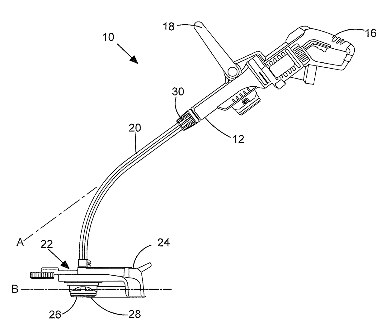
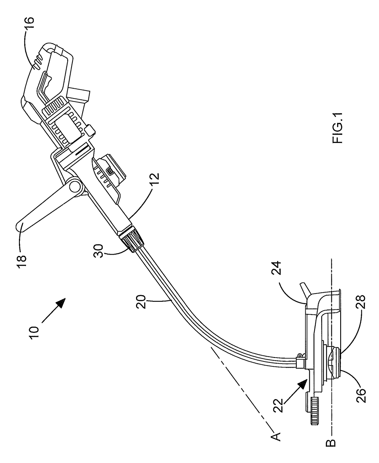
[0034]FIG. 1 shows a side view of a vegetation cutting device 10. Typically the vegetation cutting device 10 is a string trimmer, but the vegetation cutting device can alternatively be other devices suitable for cutting vegetation like brush cutters. The vegetation cutting device 10 comprises a housing 12 for housing a motor 14 and other components which will be discussed in further detail with respect to FIG. 3. The housing 12 can comprise two clam shell portions which are fixed together to enclose the motor 14 and other components. The housing 12 has a first gripping handle 16 and a second gripping handle 18 so that the vegetation cutting device 10 can be operated with two hands by a user. The housing 12 is rotatably coupled to a first end of a shaft 20 and a cutting head 22 is fixed to a second end of the shaft 20. The cutting head 22 comprises a guard 24 and a rotary cutting means 26. The rotary cutting means 26 may comprise a flexible line element which is suitable for cutting ...


PUM

PropertyMeasurementUnit
speedaaaaaaaaaa
voltageaaaaaaaaaa
voltage duty cycleaaaaaaaaaa

Abstract

A vegetation cutting device comprising a housing rotatably coupled to a shaft; a cutting head comprising a rotary cutting device for cutting vegetation, the cutting head being coupled to the shaft and being arranged to move between an edging mode in which the rotary cutting device rotates in a substantially horizontal plane; a motor mounted in the housing, the motor being arranged to drive the rotary cutting device; and a switching device mechanically coupled between the housing and the shaft and arranged to be actuated when the shaft rotates relatives to the housing thereby changing the speed of the rotary cutting device when the cutting head moves between the edging mode and trimming mode.

Description

CROSS-REFERENCE TO RELATED APPLICATIONS[0001]This application claims priority to European Patent Application No. 12190115.1 filed Oct. 26, 2012. The entire contents of that application are expressly incorporated herein by reference.FIELD OF THE INVENTION[0002]The present invention relates to a vegetation cutting device such as a string trimmer.BACKGROUND OF THE INVENTION[0003]Vegetation cutting devices such as string trimmers are known power operated tools for cutting grass and other foliage and vegetation. Typically string trimmers are powered by petrol or electricity and an engine or motor drives a cutting head. The cutting head can comprise one or more rotating blades, in which case the trimmer is generally known as a brush cutter or one or more rotating lines, in which case it is known as a string trimmer. Many types of vegetation cutting devices, such as string trimmers employ a mechanism for allowing the user of the string trimmer to operate the string trimmer in a horizontal ...

Claims


Application Information

Patent Timeline
Patent Type & Authority Patents(United States)
IPC IPC(8): B26B7/00A01D34/412A01D34/82A01D34/84A01D34/90
CPCA01D34/412A01D34/826A01D34/84A01D34/90Y10T83/9495
Inventor PROUDLOCK, DAVIDWALMSLEY, NEIL
Owner BLACK & DECKER INC
Why Eureka
Try Eureka