
Magnetic bearing structure and turbo machine having the same

a technology of magnetic bearings and turbo machines, which is applied in the direction of bearings, shafts and bearings, dynamo-electric machines, etc., can solve the problems of difficult magnetization methods and worsening the production efficiency of magnetic bearings, and achieve the effect of improving the productivity of magnetic bearings and facilitating the magnetization of permanent magnets

Active Publication Date: 2015-05-26
KOREA INST OF MACHINERY & MATERIALS
View PDF30 Cites 1 Cited by
  • Summary
  • Abstract
  • Description
  • Claims
  • Application Information

AI Technical Summary

Benefits of technology

[0010]The present invention has been made in an effort to provide a magnetic bearing structure for dividing paths of magnetic fields of an electromagnet and a permanent magnet to intercept interference of the paths thereof and to provide easy magnetization of the permanent magnet, and a turbo machine having the same.
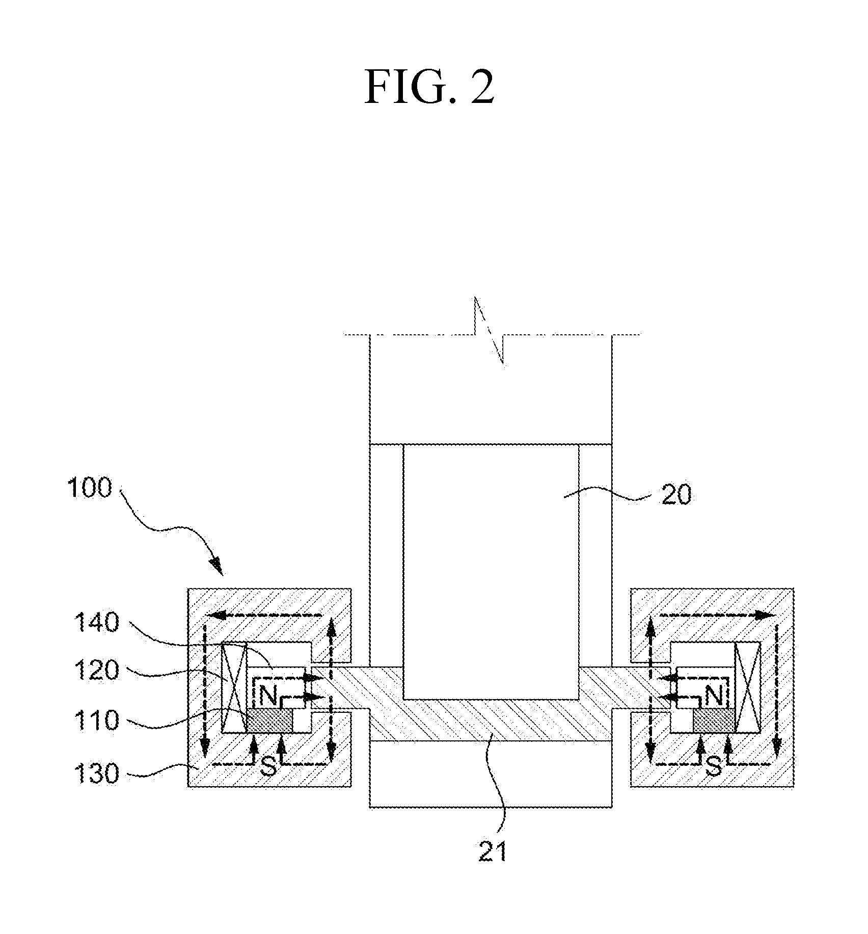
[0023]According to the embodiments of the present invention, the paths of the magnetic fields of the electromagnet and the permanent magnet are divided, an additional bias current is not applied to the electromagnet by the bias magnetic field caused by the permanent magnet, and the magnetized direction of the permanent magnet corresponds to the shaft direction of the rotation body, thereby facilitating magnetization of the permanent magnet and improving productivity of the magnetic bearing.

Problems solved by technology

However, the magnetization method is difficult and production efficiency of the magnetic bearings can be worsened.

Method used


Image

  • Magnetic bearing structure and turbo machine having the same
  • Magnetic bearing structure and turbo machine having the same
  • Magnetic bearing structure and turbo machine having the same

Examples


Embodiment Construction

[0028]Exemplary embodiments of the present invention will now be described in detail with reference to accompanying drawings.

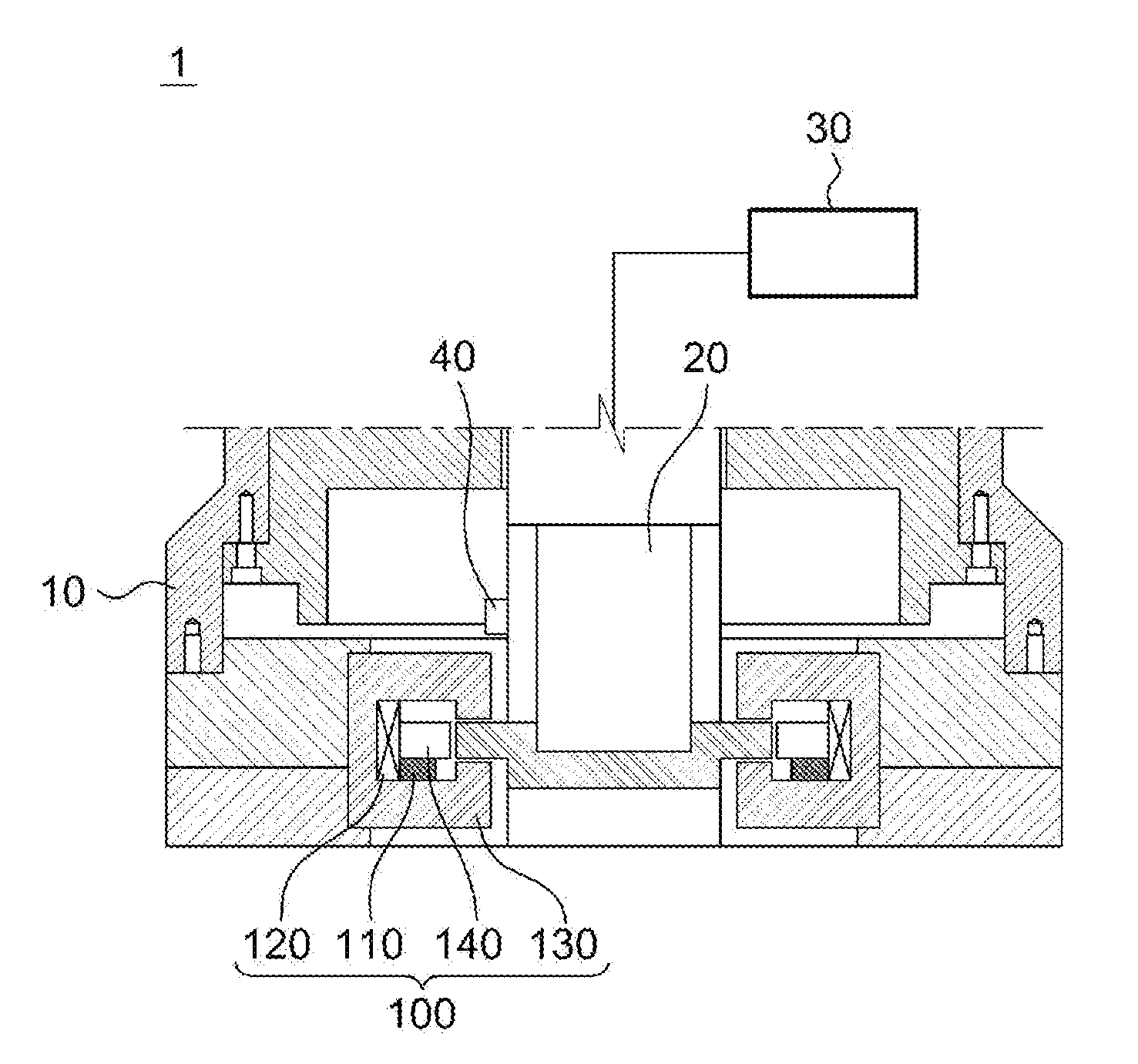
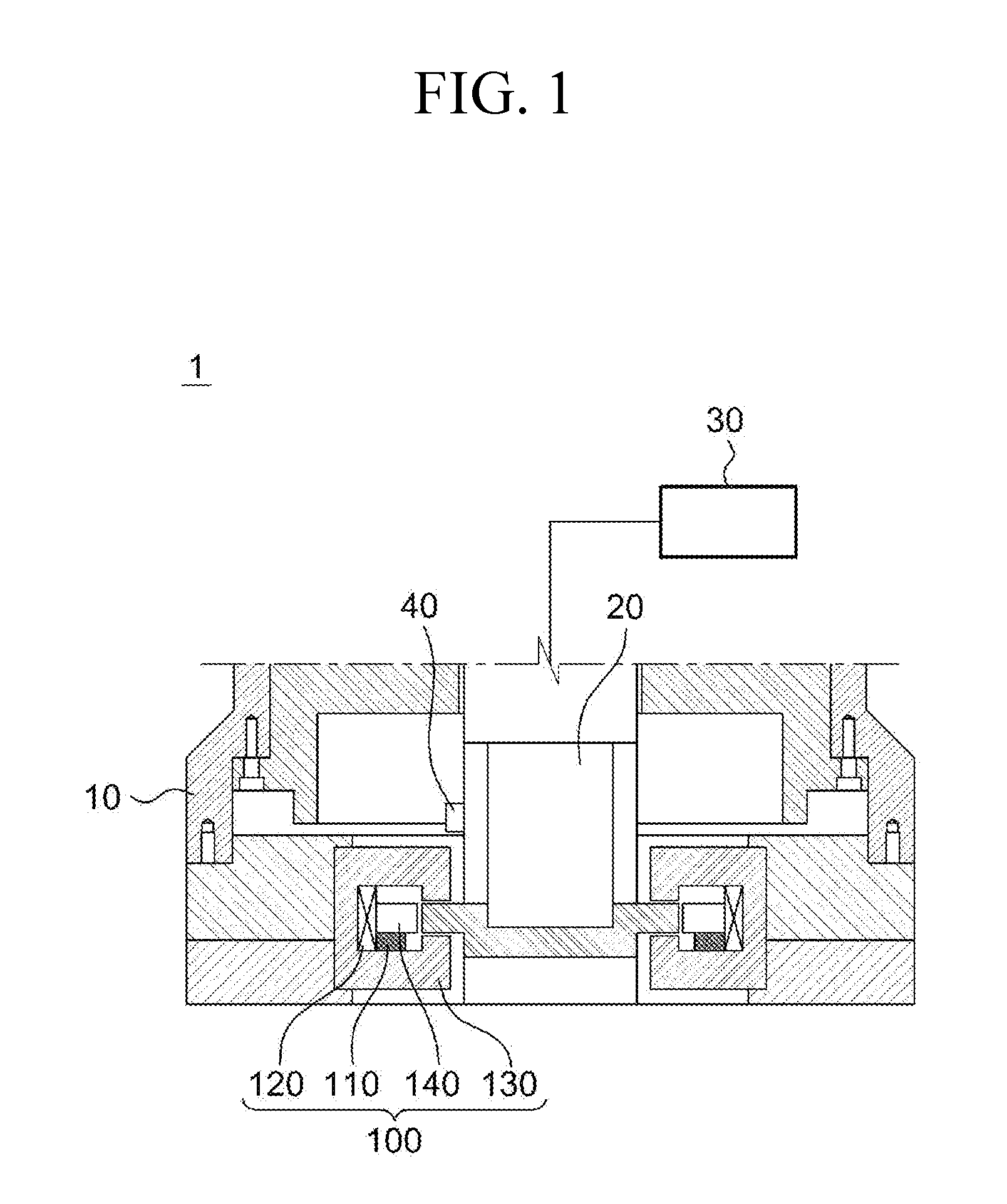
[0029]FIG. 1 shows a cross-sectional view of a turbo machine 1 with a magnetic bearing structure according to an exemplary embodiment of the present invention.

[0030]The turbo machine 1 according to an exemplary embodiment of the present invention includes a housing 10, a rotation shaft 20, a power transmitter 30, and a magnetic bearing 100. The turbo machine 1 includes a multi-purpose turbo machine used for a general machine tool, and particularly includes a small turbo machine.

[0031]The housing 10 provides a space for receiving the rotation shaft 20, and the rotation shaft 20 covers a case in which the rotation shaft is driven while it is set to be perpendicular and a case in which it is driven while it is set to be horizontal. The power transmitter 30 includes a generally-used motor, and the power transmitter 30 can be provided inside or outside the housing ...


PUM


Abstract

Disclosed is a magnetic bearing structure including a permanent magnet, levitating a rotation body without a bias current, and easily magnetizing the permanent magnet. The magnetic bearing structure includes a ring-shaped permanent magnet provided on a side of a rotation shaft and magnetized in a direction parallel with a shaft direction of the rotation shaft, a coil installed on a side of the permanent magnet, and a conductor installed on an external side of the coil and used to form a magnetic field path. According to the configuration, when an additional bias current is not supplied to the coil installed in the magnetic bearing, a rotation body levitates according to the magnetic field caused by the permanent magnet, and a magnetized direction of the permanent magnet is in parallel with a shaft direction of the rotation shaft thereby allowing easy magnetization and increasing productivity of the magnetic bearing.

Description

CROSS-REFERENCE TO RELATED APPLICATION[0001]This application is a National Stage application of PCT / KR2011 / 001676 filed on Mar. 10, 2011, which claims priority to Korean Patent Application No. 10-2010-0021869 filed in the Korean Intellectual Property Office on Mar. 11, 2010, the entire contents of which are incorporated herein by reference.BACKGROUND OF THE INVENTION[0002](a) Field of the Invention[0003]The present invention relates to a magnetic bearing structure and a turbo machine having the same, and it particularly relates to a magnetic bearing structure for using a permanent magnet and an electromagnet in a magnetic bearing provided on a side of a rotation body to allow the electromagnet to control a position of the rotation body and allow the permanent magnet to generate a bias magnetic field, and then control a magnetized direction of the permanent magnet to correspond to a shaft direction of a rotation shaft thereby facilitating magnetization, and a turbo machine having the...

Claims


Application Information

Patent Timeline
Patent Type & Authority Patents(United States)
IPC IPC(8): H02K7/09F16C32/04
CPCF16C32/0476F16C32/0465
Inventor PARK, CHEOL HOONCHOI, SANG-KYUHAM, SANG YONGYUN, DONG-WON
Owner KOREA INST OF MACHINERY & MATERIALS
Learn More