Method of manufacturing rotor

a manufacturing method and rotor technology, applied in the field of manufacturing rotors, can solve the problems of difficult to completely prevent the sheets from being magnetized, difficult to manufacture a final product, difficult to etc., to achieve reliably prevent the respective magnet materials from being magnetized, easily magnetize the plurality of magnet materials, and reliably control the strong magnetic field

Active Publication Date: 2018-07-10
TOYOTA JIDOSHA KK
View PDF10 Cites 0 Cited by
  • Summary
  • Abstract
  • Description
  • Claims
  • Application Information

AI Technical Summary

Benefits of technology

[0011]The object of the invention is to provide a method of manufacturing a rotor that can reliably prevent a plurality of magnet materials that are assembled in a rotor core from being magnetized in the opposite direction to that of the polarization of the magnet materials in a final product, and can easily perform the magnetization by a plurality of partial magnetizations.
[0013]In the method of manufacturing the rotor of the above aspect of the invention, it is possible to generate the magnetic fields at the same time with the main coils and the sub coils of the coil group by energizing the coil group. Therefore, in each partial magnetization of the magnetizing process, it is possible to form a strong magnetic field that is generated by the main coils, which always passes through the inside of the adjacent main coils or sub coils. Consequently, it is possible to reliably control the strong magnetic field that is generated by the main coils, and prevent the magnet material that is not a magnetized target in this partial magnetization from being magnetized in the opposite direction to that of the polarization in the rotor of the final product. That is, it is possible to easily magnetize the plurality of magnet materials that are assembled in the rotor core by the plurality of partial magnetizations while reliably preventing the respective magnet materials from being magnetized in the opposite direction to that of the polarization of them in the final product.
[0014]Further, in the method of manufacturing the rotor as described above, the rotor may, for each pole, have a first magnet that is arranged to face the outer peripheral surface of the rotor core, and second and third magnets that both are arranged to incline with respect to the radial direction of the rotor core and to become far away from each other as closing to the radial outside of the rotor core and that face the surface of the first magnet closing to the inner peripheral side of the rotor core. In such a rotor having three magnets for each pole, a part of each of the second magnet and the third magnet is arranged at the inside of the rotor core. Therefore, in the magnetizing process for manufacturing the rotor having three magnets for each pole, it is necessary to generate a strong magnetic field that extends to the inside of the rotor core as possible. Thus, this is because by using the magnetization device with a plurality of main coils being arranged side by side, it is possible to generate the strong magnetic field by the adjacent main coils and even make it reach the inside of the rotor core.
[0015]Further, in the method of manufacturing the rotor as described above, the magnetization device may have two coil groups, each of the coil groups may have two main coils, and a current may be capable of flowing in a circuit connected to the coil groups in a first direction and a second direction that is opposite to the first direction, a first partial magnetization, a second partial magnetization, a third partial magnetization and a fourth partial magnetization may be performed in the magnetizing process in a state of arranging the rotor core in which the magnet materials of eight poles are assembled in the magnetic field application region of the magnetization device, so as to magnetize all the magnet materials of the eight poles, in the first partial magnetization, the current may be caused to flow in the first direction, in the second partial magnetization, at a rotational position after a position of the rotor core with respect to the coil groups is rotated by 90° or 270° in a first rotation direction from a first position relationship, the current may be caused to flow in the first direction, wherein the first position relationship may be a position relationship between the rotor core and the coil groups in the first partial magnetization, in the third partial magnetization, at a rotational position after the position of the rotor core with respect to the coil groups is rotated by 135° or 315° in the first rotation direction from the first position relationship, the current may be caused to flow in the second direction, in the fourth partial magnetization, at a rotational position after the position of the rotor core with respect to the coil groups is rotated by 45° or 225° in the first rotation direction from the first position relationship, the current may be caused to flow in the second direction. This is because it is possible to magnetize all the magnet materials of the eight poles that are assembled in the rotor core while reliably preventing the respective magnet materials from being magnetized in the opposite direction to that of the polarization of them in the final product.
[0016]Further, in the method of manufacturing the rotor as described above, the magnetization device may have one coil group, the coil groups may have has three main coils, and a current may be capable of flowing in a circuit connected to the coil group in a first direction, a first partial magnetization, a second partial magnetization, a third partial magnetization and a fourth partial magnetization may be performed in the magnetizing process in a state of arranging the rotor core in which the magnet materials of eight poles are assembled in the magnetic field application region of the magnetization device, so as to magnetize all the magnet materials of the eight poles, in the first partial magnetization, the current may be caused to flow in the first direction, in the second partial magnetization, at a rotational position after a position of the rotor core with respect to the coil group is rotated by 180° in a first rotation direction from a first position relationship, the current may be caused to flow in the first direction, wherein the first position relationship may be a position relationship between the rotor core and the coil group in the first partial magnetization, in the third partial magnetization, at a rotational position after the position of the rotor core with respect to the coil group is rotated by 270° in the first rotation direction from the first position relationship, the current may be caused to flow in the first direction, in the fourth partial magnetization, at a rotational position after the position of the rotor core with respect to the coil group is rotated by 90° in the first rotation direction from the first position relationship, the current may be caused to flow in the first direction. This is because it is possible to magnetize all the magnet materials of the eight poles that are assembled in the rotor core while reliably preventing the respective magnet materials from being magnetized in the opposite direction to that of the polarization of them in the final product. Further, since the number of coils is reduced, it is possible to reduce a voltage applied to the circuit that is connected to the coil group. In addition, since there is no need to switch a flow direction of the current, it is possible to use an inexpensive magnetization device.
[0017]According to the above aspect of the invention, it is possible to provide a method for manufacturing a rotor that can easily magnetize a plurality of magnet materials that are assembled in a rotor core by a plurality of partial magnetizations while reliably prevent the respective magnet materials from being magnetized in the opposite direction to that of the polarization in a final product.

Problems solved by technology

Also, depending on an arrangement of a plurality of magnet materials in the rotor, sometimes it is difficult to magnetize them all by applying an external magnetic field once.
For example, it is difficult to manufacture a final product by polarizing reversely a magnet that has been polarized in the opposite direction by an external magnetic field applied previously.
For this reason, there is a problem that it is very difficult to completely prevent the sheets to be magnetized that are not magnetized targets from being polarized reversely by the magnetic fields for magnetizing.

Method used


Image

  • Method of manufacturing rotor
  • Method of manufacturing rotor
  • Method of manufacturing rotor

Examples


first embodiment

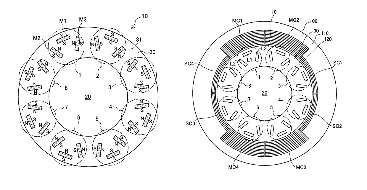
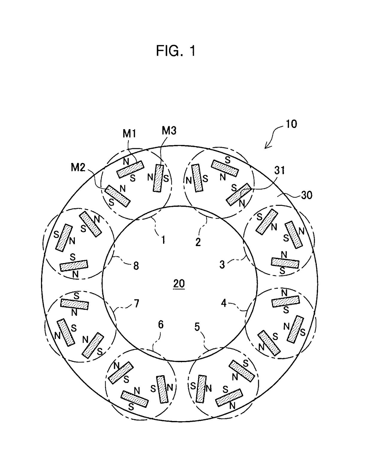
[0033]First, a rotor manufactured by the method of manufacturing the rotor according to the embodiment will be described. FIG. 1 is a schematic top view of the rotor 10 according to the embodiment. As shown in FIG. 1, the rotor 10 is configured by assembling a rotor core 30 to the outer periphery of a shaft 20. In addition, a plurality of magnets M1, M2, M3 are assembled in the rotor core 30. Specifically, as indicated by a dashed line in FIG. 1, the rotor core 30 has eight groups from group 1 to group 8, each of which is configured of one magnet M1, one magnet M2 and one magnet M3.

[0034]The rotor core 30 is formed by laminating a plurality of electromagnetic steel sheets in a depth direction in FIG. 1. Moreover, holes are formed at the same positions in the laminated electromagnetic steel sheets, and a plurality of slots 31 are formed in the rotor core 30 by overlapping the holes. Thus, the magnets M1, M2, M3 are mounted in each slot 31 of the rotor core 30.

[0035]The magnets M1, M2...

second embodiment

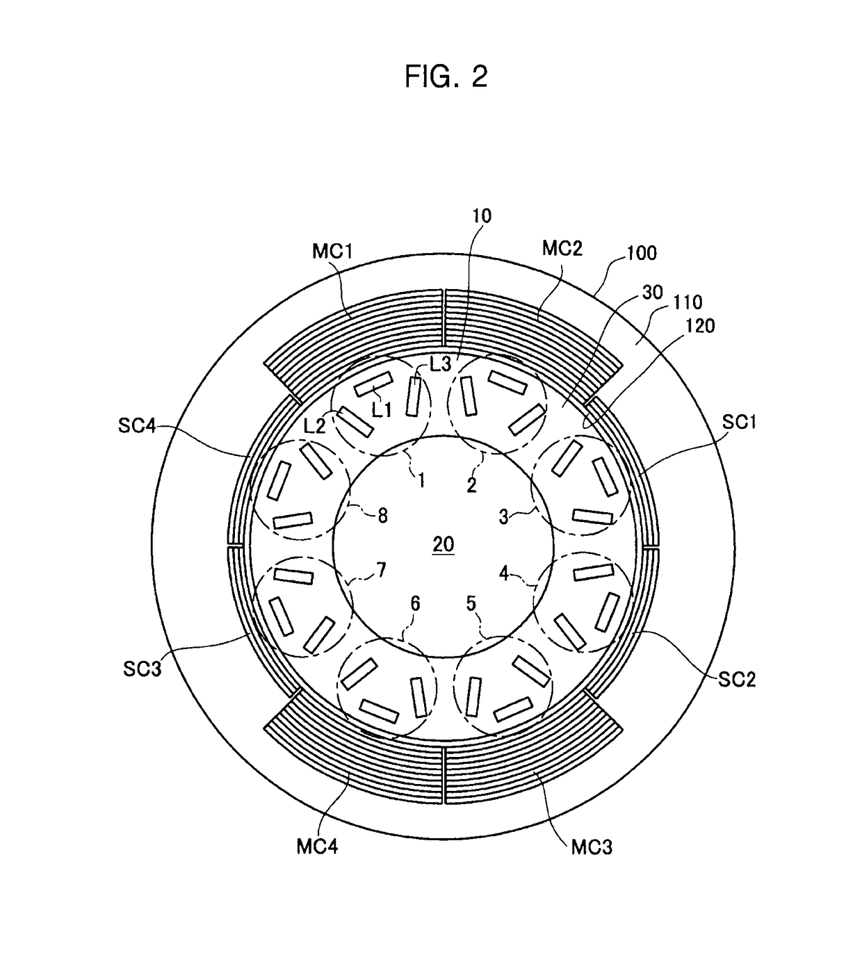
[0084]Next, a second embodiment will be described. In this embodiment, the rotor to be manufactured is the same as the rotor of the first embodiment shown in FIG. 1. In the present embodiment, a magnetizing process of a magnetization device that is different from that of the first embodiment is used. Specifically, the magnetization device with the number and arrangement of the main coils and sub coils that are different from those of the first embodiment shown in FIG. 2 is used in the magnetizing process of this embodiment.

[0085]FIG. 8 shows a magnetization device 200 that is used in the magnetizing process of the second embodiment. The magnetization device 200 includes a core portion 210, main coils MC1, MC2, MC3, and sub coils SC1, SC2. In this embodiment, when it is not particularly distinguished between the main coils MC1, MC2, MC3, they are referred to as main coils MC, and when it is not particularly distinguished between the sub coils SC1, SC2, they are referred to as sub coi...


PUM


Abstract

The invention relates to a method of manufacturing a rotor for performing a magnetizing process of magnetizing a plurality of magnet materials that are assembled in a rotor core. A magnetization device is used which has a coil group configured of a plurality of coils that are disposed side by side in a manner that winding directions of adjacent coils are opposite to each other, the coil group is configured of sub coils at both ends and two or more main coils between the sub coils, and all of the coils are connected in series. Further, in the magnetizing process, a partial magnetization of magnetizing the magnet material among the plurality of magnet materials to which magnetic flux interlinking with two adjacent main coils is applied is performed a plurality of times, so as to magnetize all the plurality of magnet materials.

Description

INCORPORATION BY REFERENCE[0001]The disclosure of Japanese Patent Application No. 2014-187156 filed on Sep. 15, 2014 including the specification, drawings and abstract is incorporated herein by reference in its entirety.BACKGROUND OF THE INVENTION[0002]1. Field of the Invention[0003]The invention relates to a method of manufacturing a rotor that can be used in an electric motor or a generator, and more particularly, relates to a method of manufacturing a rotor by magnetizing separately a plurality of magnet materials embedded in a rotor core in a plurality of times.[0004]2. Description of Related Art[0005]Conventionally, as a rotor used in an electric motor or a generator, there is a rotor with a plurality of magnets that are embedded in a rotor core formed by laminating steel sheets. For example, such a rotor can be manufactured by embedding an unmagnetized magnet material in the rotor core and magnetizing the embedded magnet material.[0006]The magnet material embedded in the rotor...

Claims


Application Information

Patent Timeline
Patent Type & Authority Patents(United States)
IPC IPC(8): H02K15/03
CPCH02K15/03
Inventor OKADA, ICHIROURANO, HIROAKITATEBE, KATSUHIKOTANAHASHI, FUMIKIHORI, MICHITAKA
Owner TOYOTA JIDOSHA KK
Why Eureka
Try Eureka