Deposition mask, vapor deposition apparatus, vapor deposition method, and method for manufacturing organic EL display apparatus

a technology of vapor deposition mask and vapor deposition substrate, which is applied in the direction of vacuum evaporation coating, solid-state devices, coatings, etc., can solve the problems of inability to etch organic layers and easy moisture, and achieve the effect of easy separation between the deposition mask and the substrate for vapor deposition, stable time for vapor deposition, and reliable separation of the deposition mask and the substra

Active Publication Date: 2021-01-12
HON HAI PRECISION IND CO LTD
View PDF17 Cites 0 Cited by
  • Summary
  • Abstract
  • Description
  • Claims
  • Application Information

AI Technical Summary

Benefits of technology

[0012]According to the vapor deposition method of the present invention, a metal layer (metal support layer) of the deposition mask, which is made of a ferromagnetic material, is magnetized. This deposition mask is attracted and fixed to a magnetic chuck together with a substrate for vapor deposition, and then the substrate for vapor deposition is vapor-deposited. After the vapor deposition, a direction of current fed through the magnetic chuck is controlled such that a magnetic field is generated in an orientation opposite to a magnetized orientation of the deposition mask. In this way, the deposition mask can be separated easily. Further, the deposition mask is always magnetized in a certain orientation. Thus, an electromagnet can uniformly and constantly apply a magnetic field in the opposite direction, thereby reliably separating the deposition mask and the substrate for vapor deposition from each other. As a result, a time for the vapor deposition is always stable in a manufacturing process, and a long time is not required for the separation. Consequently, it is possible to continue the process in a stable process working time (so-called tact time). Even when the substrate for vapor deposition and the deposition mask are aligned with each other, the electromagnet can weaken its magnetic field to suppress excessive attraction. This enables the substrate for vapor deposition to be finely moved, thereby facilitating the alignment between the substrate for vapor deposition and the deposition mask.
[0013]According to a vapor deposition apparatus of the present invention, an electromagnet provided in the vapor deposition apparatus has a control circuit that can magnetize a metal layer of a deposition mask. Thus, before or after the deposition mask is aligned with the vapor deposition apparatus together with the substrate for vapor deposition, the electromagnet can easily magnetize the metal layer. If the metal layer has already been magnetized before the deposition mask and the substrate for vapor deposition are aligned with and overlaid on each other, the electromagnet can, during the alignment, generate a magnetic field in an orientation opposite to a magnetized orientation of the metal layer, thereby weakening the attractive force.
[0014]According to the deposition mask of the present invention, the metal layer of the deposition mask is already magnetized in a certain orientation. The electromagnet in the vapor deposition apparatus can generate a magnetic field in the opposite direction, thereby easily separating the deposition mask and a substrate for vapor deposition from each other. In this case, since the deposition mask is magnetized in the certain orientation, the magnetic field generated in the opposite direction is also always constant. Therefore, the separation can be reliably made in a short time.
[0015]According to the method for manufacturing the organic EL display apparatus of the present invention, the deposition mask is always magnetized in a certain orientation. After vapor deposition, therefore, a process of separating the deposition mask and the electromagnet from each other is performed while an electromagnet is generating a magnetic field in an orientation opposite to the magnetized orientation of the deposition mask. In this way, the deposition mask and the electromagnet are easily separated from each other. Consequently, this method makes it possible to perform a vapor deposition process within a given time in any situation, in other words, to finish the vapor deposition process within a stable time, thereby contributing to achievement of cost reduction.

Problems solved by technology

These organic layers are susceptible to moisture and thus cannot be etched.
However, to form a deposition mask having a fine pattern of opening sections, a resin film instead of the metal mask, furthermore, a complex type deposition mask in which the resin film and a metal film are stacked to maintain a mechanical strength of the resin film, tends to be used.

Method used


Image

  • Deposition mask, vapor deposition apparatus, vapor deposition method, and method for manufacturing organic EL display apparatus
  • Deposition mask, vapor deposition apparatus, vapor deposition method, and method for manufacturing organic EL display apparatus
  • Deposition mask, vapor deposition apparatus, vapor deposition method, and method for manufacturing organic EL display apparatus

Examples


Embodiment Construction

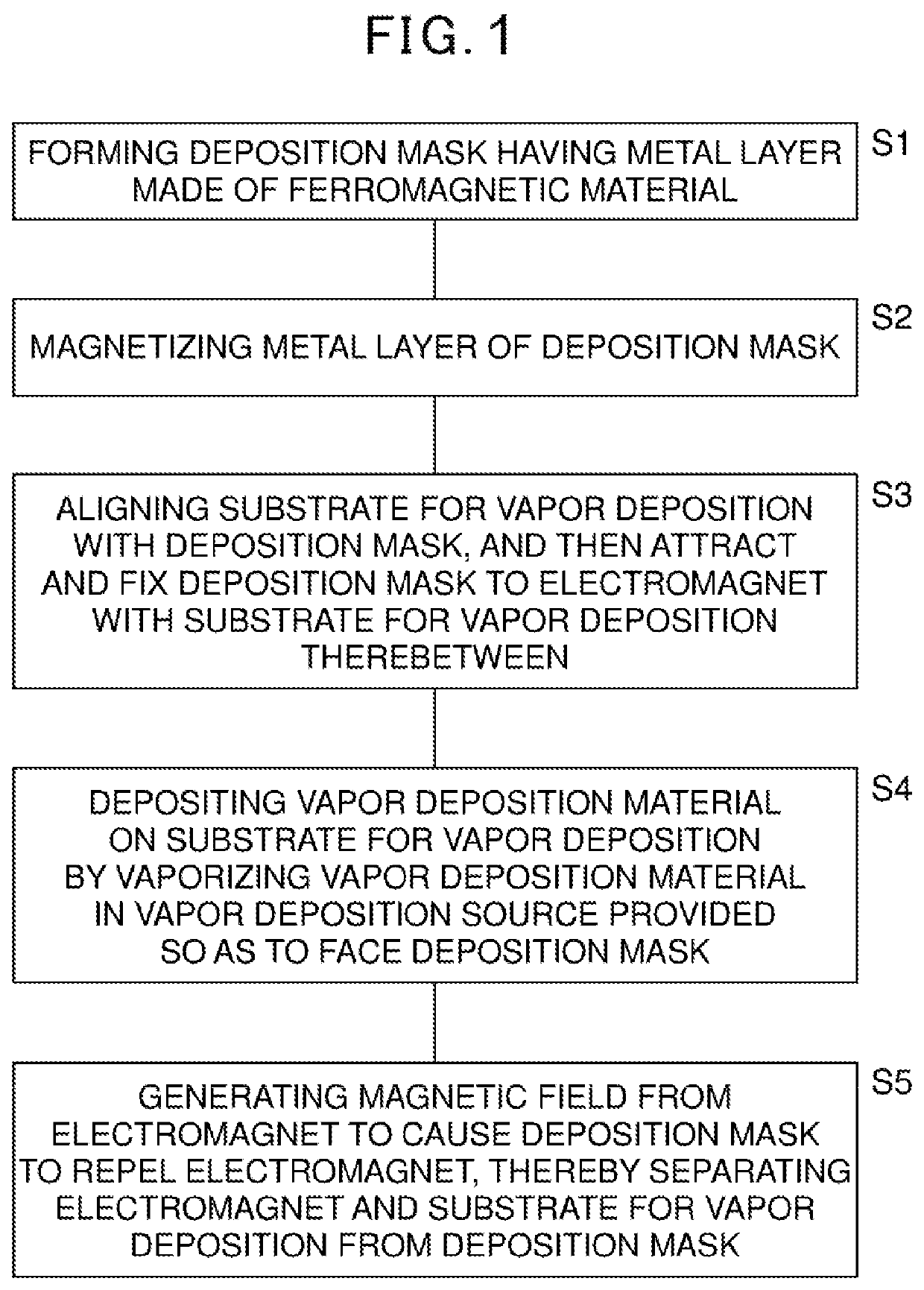
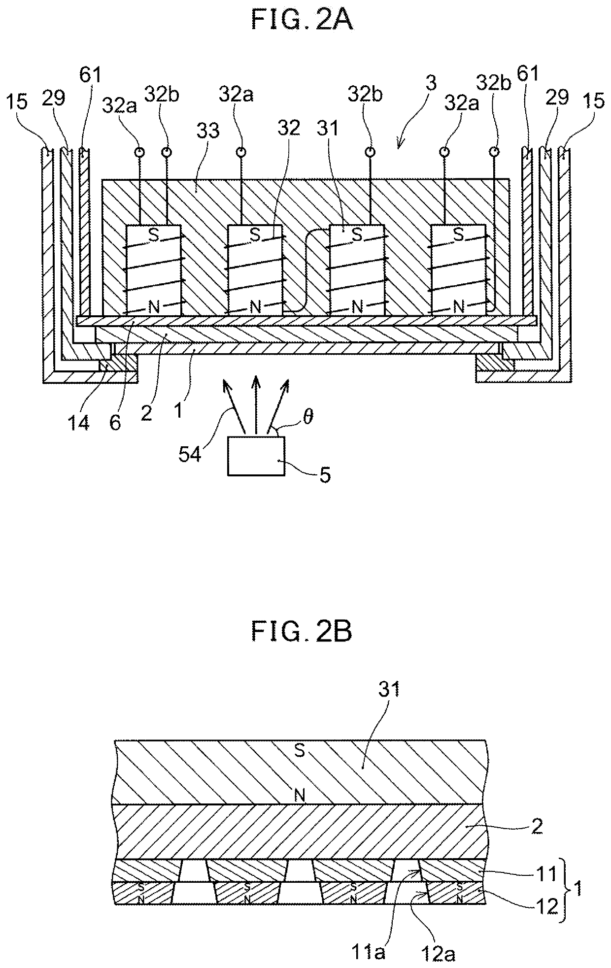
[0026]With reference to the accompanying drawings, a description will be given of a vapor deposition method, a vapor deposition apparatus, and a deposition mask of the present invention. A process chart of an embodiment of the deposition method of the present invention is shown in FIG. 1, and a schematic view of a deposition apparatus for vapor deposition is shown in FIGS. 2A and 2B. As illustrated in FIGS. 1 to 2B respectively, the vapor deposition method comprising: forming a deposition mask 1 having at least partly a metal layer (metal support layer) 12 made of a ferromagnetic material (S1); magnetizing the metal layer 12 of the deposition mask 1 by applying a magnetic field to the metal layer 12 (S2); aligning the deposition mask 1 and a substrate 2 for vapor deposition with each other, and then attracting and fixing the deposition mask 1 to an electromagnet 3 with the substrate 2 for vapor deposition therebetween (S3); depositing a vapor deposition material on the substrate 2 f...


PUM

PropertyMeasurementUnit
thicknessaaaaaaaaaa
thicknessaaaaaaaaaa
thicknessaaaaaaaaaa

Abstract

The present application provides a vapor deposition method, a deposition mask, and a vapor deposition apparatus that make it possible to reliably and uniformly separate the deposition mask in a short time after vapor deposition is performed using a vapor deposition material. In Step (S1), a deposition mask that at least partly has a metal layer (metal support layer) made of a ferromagnetic material is formed. In Step (S2), the metal layer of the deposition mask is magnetized by applying an electromagnetic field to the metal layer. In Step (S3), the deposition mask and a substrate are aligned with each other, and then the deposition mask is attracted and fixed to an electromagnet with the substrate) therebetween. In Step (S4), a vapor deposition source is disposed so as to face the deposition mask, and a vapor deposition material in the vapor deposition source is deposited on the substrate by vaporizing the vapor deposition material. In Step (S5), the electromagnet generates a magnetic field to cause the deposition mask to repel the electromagnet, thereby separating both the electromagnet and the substrate from the deposition mask.

Description

TECHNICAL FIELD[0001]The present invention relates to a deposition mask, a vapor deposition apparatus, a vapor deposition method, for example, which are used to vapor-deposit an organic layer in the organic electro-luminescence (EL) display apparatus, and a method for manufacturing an organic EL display apparatus. More specifically, the present invention relates to a deposition mask, a vapor deposition apparatus, a vapor deposition method, which make it possible to easily separate the deposition mask during vapor deposition, and a method for manufacturing an organic EL display apparatus.BACKGROUND ART[0002]For example, when an organic EL display apparatus is manufactured, a device substrate is formed by forming switching elements such as thin-film-transistors (TFTs) on a support substrate, and then organic layers are deposited on this device substrate in each of pixels. These organic layers are susceptible to moisture and thus cannot be etched. Thus, a deposition mask is disposed ov...

Claims


Application Information

Patent Timeline
Patent Type & Authority Patents(United States)
IPC IPC(8): H01L29/08H01L51/00C23C14/50C23C14/12C23C14/24C23C14/04H01L51/50H01L51/56
CPCH01L51/0011C23C14/042C23C14/12C23C14/24C23C14/50H01L51/5012H01L51/56H10K71/166H10K71/00H10K50/11
Inventor NISHIDA, KOSHIKISHIMOTO, KATSUHIKO
Owner HON HAI PRECISION IND CO LTD
Why Eureka
Try Eureka