
Method of manufacturing rotor

a manufacturing method and rotor technology, applied in the direction of solid insulation, dynamo-electric machines, electrical apparatus, etc., can solve the problems of difficult to completely prevent sheets from being magnetized, difficult to manufacture a final product, and difficult to completely control the magnetic field, so as to reliably prevent the respective magnet material from being magnetized, easily magnetize the plurality of magnet materials, and reliably control the strong magnetic field

Active Publication Date: 2016-03-17
TOYOTA JIDOSHA KK
View PDF5 Cites 1 Cited by
  • Summary
  • Abstract
  • Description
  • Claims
  • Application Information

AI Technical Summary

Benefits of technology

The invention provides a method for manufacturing a rotor that can prevent magnet materials from being magnetized in the opposite direction to the final product, while still easily performing partial magnetizations. The method involves generating magnetic fields using a coil group, which can be arranged to face the rotor core and reliably control the magnetic field. The rotor may also have additional magnets that are inclined to face the inner surface of the rotor core, ensuring a strong magnetic field that reaches the inside of the rotor core. The method can also use a magnetization device with multiple coil groups and main coils to easily perform partial magnetizations and prevent magnet materials from being magnetized in the opposite direction. Overall, the method allows for reliable and efficient magnetization of the rotor while preventing unwanted magnetization.

Problems solved by technology

Also, depending on an arrangement of a plurality of magnet materials in the rotor, sometimes it is difficult to magnetize them all by applying an external magnetic field once.
For example, it is difficult to manufacture a final product by polarizing reversely a magnet that has been polarized in the opposite direction by an external magnetic field applied previously.
For this reason, there is a problem that it is very difficult to completely prevent the sheets to be magnetized that are not magnetized targets from being polarized reversely by the magnetic fields for magnetizing.

Method used


Image

  • Method of manufacturing rotor
  • Method of manufacturing rotor
  • Method of manufacturing rotor

Examples


first embodiment

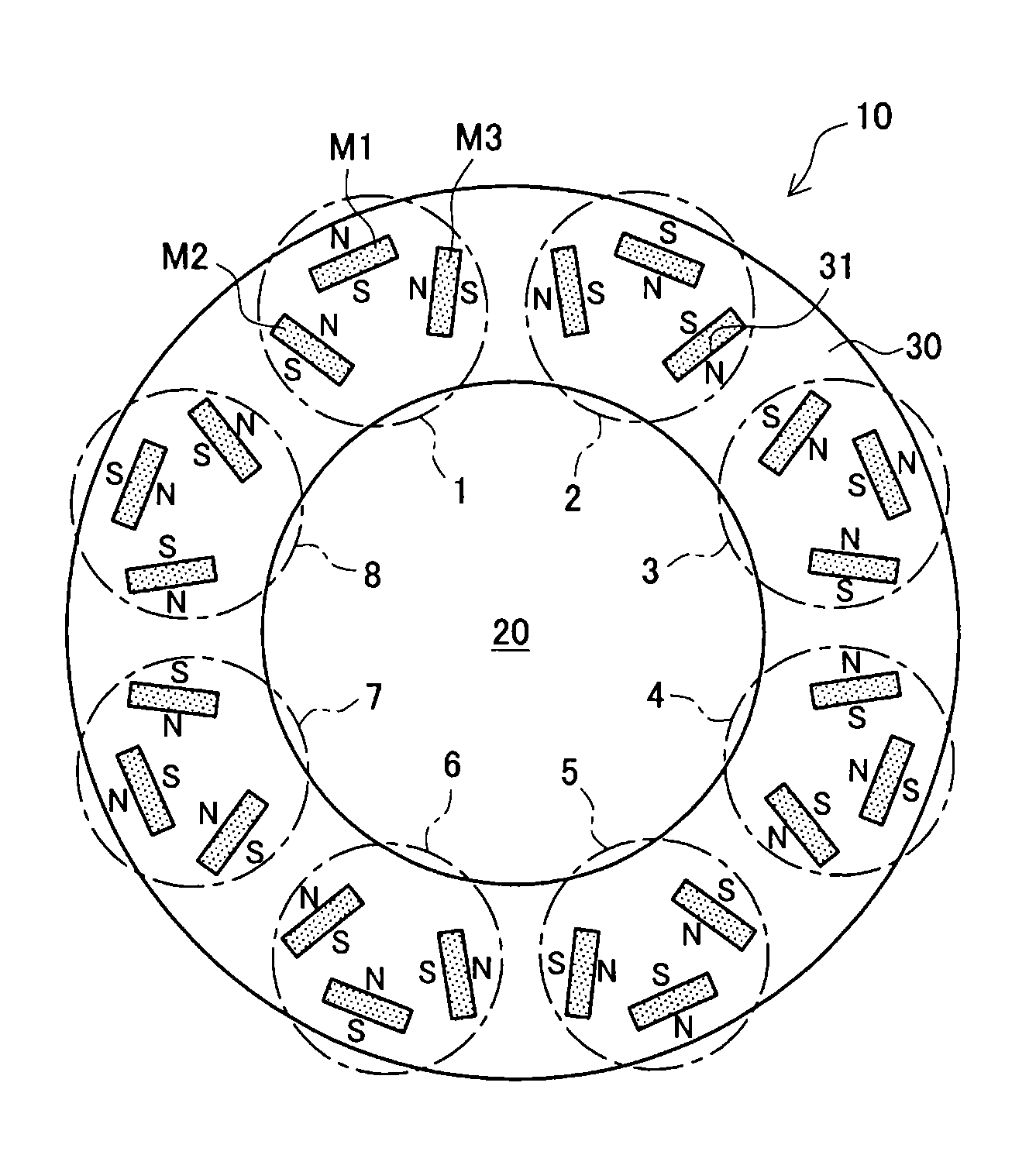
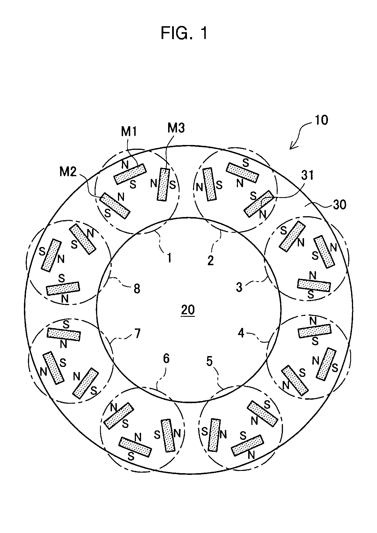
[0033]First, a rotor manufactured by the method of manufacturing the rotor according to the embodiment will be described. FIG. 1 is a schematic top view of the rotor 10 according to the embodiment. As shown in FIG. 1, the rotor 10 is configured by assembling a rotor core 30 to the outer periphery of a shaft 20. In addition, a plurality of magnets M1, M2, M3 are assembled in the rotor core 30. Specifically, as indicated by a dashed line in FIG. 1, the rotor core 30 has eight groups from group 1 to group 8, each of which is configured of one magnet M1, one magnet M2 and one magnet M3.

[0034]The rotor core 30 is formed by laminating a plurality of electromagnetic steel sheets in a depth direction in FIG. 1. Moreover, holes are formed at the same positions in the laminated electromagnetic steel sheets, and a plurality of slots 31 are formed in the rotor core 30 by overlapping the holes. Thus, the magnets M1, M2, M3 are mounted in each slot 31 of the rotor core 30.

[0035]The magnets M1, M2...

second embodiment

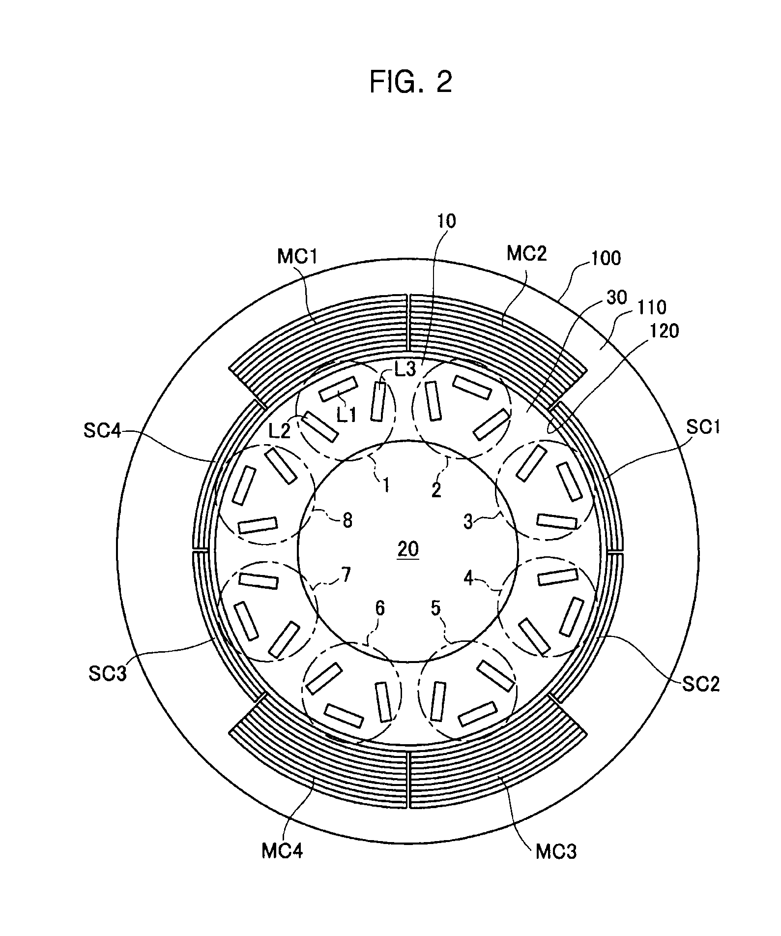
[0084]Next, a second embodiment will be described. In this embodiment, the rotor to be manufactured is the same as the rotor of the first embodiment shown in FIG. 1. In the present embodiment, a magnetizing process of a magnetization device that is different from that of the first embodiment is used. Specifically, the magnetization device with the number and arrangement of the main coils and sub coils that are different from those of the first embodiment shown in FIG. 2 is used in the magnetizing process of this embodiment.

[0085]FIG. 8 shows a magnetization device 200 that is used in the magnetizing process of the second embodiment. The magnetization device 200 includes a core portion 210, main coils MC1, MC2, MC3, and sub coils SC1, SC2. In this embodiment, when it is not particularly distinguished between the main coils MC1, MC2, MC3, they are referred to as main coils MC, and when it is not particularly distinguished between the sub coils SC1, SC2, they are referred to as sub coi...


PUM


Abstract

The invention relates to a method of manufacturing a rotor for performing a magnetizing process of magnetizing a plurality of magnet materials that are assembled in a rotor core. A magnetization device is used which has a coil group configured of a plurality of coils that are disposed side by side in a manner that winding directions of adjacent coils are opposite to each other, the coil group is configured of sub coils at both ends and two or more main coils between the sub coils, and all of the coils are connected in series. Further, in the magnetizing process, a partial magnetization of magnetizing the magnet material among the plurality of magnet materials to which magnetic flux interlinking with two adjacent main coils is applied is performed a plurality of times, so as to magnetize all the plurality of magnet materials.

Description

INCORPORATION BY REFERENCE[0001]The disclosure of Japanese Patent Application No. 2014-187156 filed on Sep. 15, 2014 including the specification, drawings and abstract is incorporated herein by reference in its entirety.BACKGROUND OF THE INVENTION[0002]1. Field of the Invention[0003]The invention relates to a method of manufacturing a rotor that can be used in an electric motor or a generator, and more particularly, relates to a method of manufacturing a rotor by magnetizing separately a plurality of magnet materials embedded in a rotor core in a plurality of times.[0004]2. Description of Related Art[0005]Conventionally, as a rotor used in an electric motor or a generator, there is a rotor with a plurality of magnets that are embedded in a rotor core formed by laminating steel sheets. For example, such a rotor can be manufactured by embedding an unmagnetized magnet material in the rotor core and magnetizing the embedded magnet material.[0006]The magnet material embedded in the rotor...

Claims


Application Information

Patent Timeline
Patent Type & Authority Applications(United States)
IPC IPC(8): H02K15/03
CPCH02K15/03
Inventor OKADA, ICHIROURANO, HIROAKITATEBE, KATSUHIKOTANAHASHI, FUMIKIHORI, MICHITAKA
Owner TOYOTA JIDOSHA KK
Learn More