Interchangeable lens camera, camera body, lens unit, and busy signal control method

a technology of lens unit and camera body, which is applied in the direction of instruments, television systems, focusing aids, etc., can solve the problems of wasteful communication and difficult to efficiently confirm the busy state, and achieve the effect of efficiently confirming the busy sta

Active Publication Date: 2015-05-26
FUJIFILM CORP
View PDF13 Cites 15 Cited by
  • Summary
  • Abstract
  • Description
  • Claims
  • Application Information

AI Technical Summary

Benefits of technology

[0013]The present invention is made in view of these circumstances, and has an object of providing an interchangeable lens camera, camera body, lens unit, and busy signal control method capable of efficiently confirming a busy state without wasteful communications even if a plurality of types of operation can be performed.
[0015]According to the present invention, compared with the case in which an inquiry about a busy state and response are repeated in data communications, it is not required to repeat a busy inquiry and a response many times by using a busy signal indicating that now is during operation. Also, compared with the case in which a busy notification is made only for a predetermined fixed operation by simply using a busy signal, any type of an operation of a notification target of the busy signal is indicated by a busy signal control instruction, thereby selectively and efficiently monitoring a necessary operation only with the paired busy signal terminals provided to the camera body and the lens unit.
[0016]In an embodiment, the lens unit has a driven member and a driving part which drives the driven member, and at initial position driving of driving the driven member by the driving part to an initially set position, with the busy signal control instruction not received from the camera body, the communicating part of the lens unit sets the busy signal to an ON state during a period of the initial position driving, and sets the busy signal to an OFF state when the initial position driving ends. That is, by making a busy notification without using a busy signal control instruction normally used, the lens unit can quickly drive the driven member to the initially set position without waiting for the busy signal control instruction.
[0024]According to the present invention, when the camera body and the lens unit each notify its counterpart that now is during a period of an operation, a busy state can be efficiently confirmed without wasteful communication.

Problems solved by technology

However, when the camera body and the lens unit each notify its counterpart of a busy state, it is difficult to efficiently confirm the busy state without wasteful communications.
When an inquiry about a busy state and a response indicating whether the state is busy are made by using data communications as described in PTL 1, such an inquiry and response are repeated many times during a busy period, leading to wasteful communications.

Method used


Image

  • Interchangeable lens camera, camera body, lens unit, and busy signal control method
  • Interchangeable lens camera, camera body, lens unit, and busy signal control method
  • Interchangeable lens camera, camera body, lens unit, and busy signal control method

Examples


Embodiment Construction

[0032]Embodiments of the present invention are described in detail below according to the attached drawings.

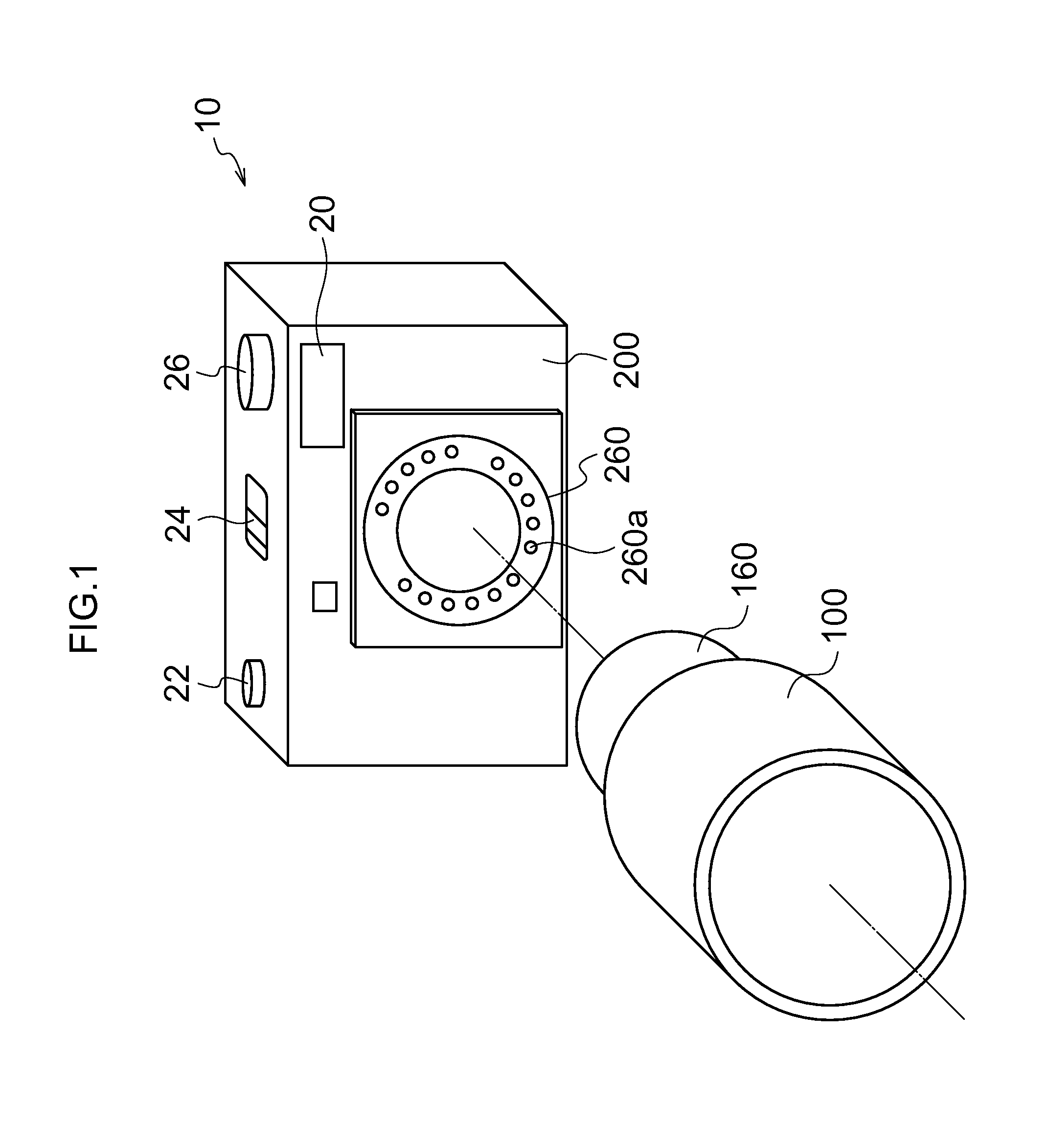
[0033]FIG. 1 is a perspective view of a front outer view of an interchangeable lens camera (hereinafter refer to a “camera”) according to an embodiment of the present invention.

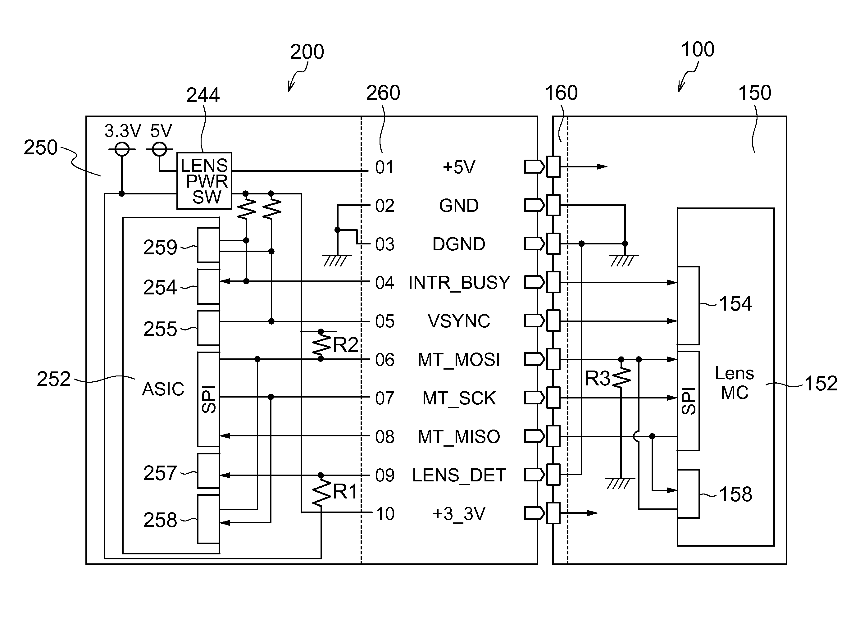
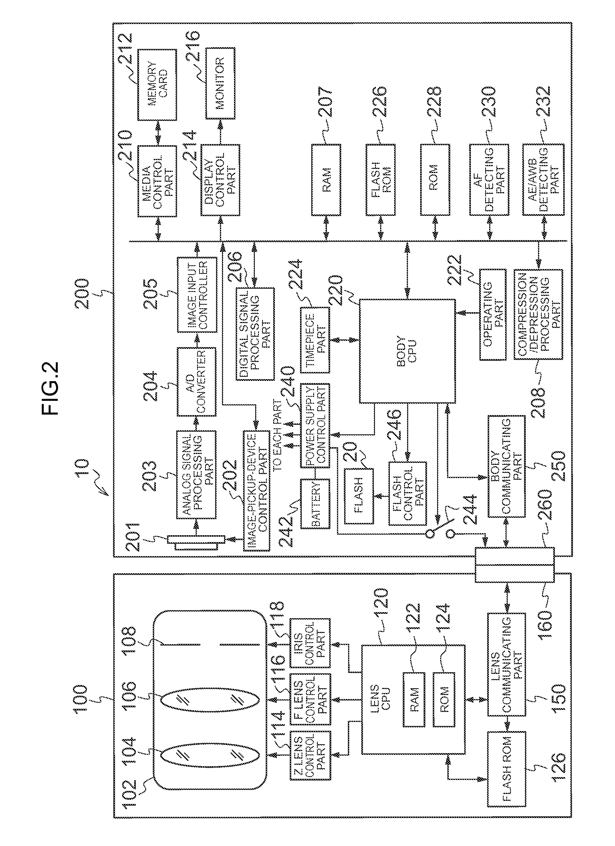
[0034]As depicted in FIG. 1, a camera 10 of the present embodiment includes a lens unit 100 and a camera body 200. The lens unit 100 includes a lens mount 160 (lens-side mount part) attachable to and detachable from a body mount 260 (body-side mount part), which will be described further below, of the camera body 200. The lens unit 100 of this example is in a cylindrical shape, and has the lens mount 160 formed at an end of the lens unit 100. The camera body 200 includes a body mount 260 to and from which the lens mount 160 of the lens unit 100 is attachable and detachable. The camera body 200 of this example is in a box shape, and has the body mount 260 formed approximately at the center of the front s...


PUM


Abstract

An aspect of the present invention provides an interchangeable lens camera having a camera body and a lens unit that is freely attachable and detachable to the camera body. In the interchangeable lens camera, a communications unit in the camera body sends via communications terminals (MT_MOSI and MT_MISO) an INTR_BUSY control instruction that instructs whether to make notification with a busy signal (INTR_BUSY signal) for any operation out of a plurality of types of operations that can be executed, and the lens unit or camera body communications unit sets the busy signal (INTR_BUSY) to an ON state (low level) only during the period of operation of the type indicated by the INTR_BUSY control instruction.

Description

CROSS-REFERENCE TO RELATED APPLICATIONS[0001]This application is a continuation application and claims the priority benefit under 35 U.S.C. §120 of PCT Application No. PCT / JP2012 / 082029 filed on Dec. 11, 2012 which application designates the U.S., and also claims the priority benefit under 35 U.S.C. §119 of Japanese Patent Application No. 2011-289517 filed on Dec. 28, 2011, which applications are all hereby incorporated by reference in their entireties.BACKGROUND OF THE INVENTION[0002]1. Field of the Invention[0003]The present invention relates to an interchangeable lens camera with an interchangeable lens unit having a taking lens, a camera body, the lens unit, and a busy signal control method.[0004]2. Description of the Related Art[0005]Interchangeable lens cameras including a camera body to and from which a lens unit with a taking lens is attachable and detachable have been widely available. General examples of an interchangeable lens camera are a single-lens reflex camera includ...

Claims


Application Information

Patent Timeline
Patent Type & Authority Patents(United States)
IPC IPC(8): H04N5/225G03B19/12G03B17/00G03B17/14H04N5/232
CPCH04N5/23209G03B17/14H04N5/23225G03B2206/00H04N23/663H04N23/673G03B13/34G03B17/18H04N23/617G03B13/36
Inventor IMAMURA, KENSHI
Owner FUJIFILM CORP
Why Eureka
Try Eureka