Active vibration noise control apparatus

a technology of active vibration and noise control, which is applied in the direction of noise generation, ear treatment, instruments, etc., can solve the problems of not being effective, abnormal sound may be produced, and overall vibration noise may be increased, so as to prevent the enhancement of noise in the passenger compartment of the vehicle, detect relatively easily, and detect relatively easily

Active Publication Date: 2015-05-26
HONDA MOTOR CO LTD
View PDF9 Cites 1 Cited by
  • Summary
  • Abstract
  • Description
  • Claims
  • Application Information

AI Technical Summary

Benefits of technology

[0008]The present invention has been made in view of the above drawbacks. It is an object of the present invention to provide an active vibration noise control apparatus which is capable of increasing a sound silencing capability.
[0010]According to the present invention, the noise in the passenger compartment of the vehicle is prevented from being enhanced or an abnormal sound is prevented from being generated in the passenger compartment by the rear road wheel canceling sound which would otherwise be intensively produced due to the different paths followed by the front road wheel and the rear road wheel.
[0011]The canceling sound output unit may detect that the path followed by the front road wheel and the path followed by the rear road wheel are different from each other if a steering quantity representing the steered state is greater than a first threshold value. By comparing the steering quantity and the threshold value (first threshold value) with respect to the steering quantity with each other, it is possible to detect relatively easily that the paths followed by the front road wheel and the rear road wheel are different from each other.
[0012]The canceling sound output unit may detect that the path followed by the front road wheel and the path followed by the rear road wheel are different from each other if a steering rate representing the steered state is greater than a second threshold value. By comparing the steering rate and the threshold value (second threshold value) with respect to the steering rate with each other, it is possible to detect relatively easily that the paths followed by the front road wheel and the rear road wheel are different from each other.
[0013]The canceling sound output unit may suppress output of the rear road wheel canceling sound for a predetermined period after having detected that the path followed by the front road wheel and the path followed by the rear road wheel are different from each other based on the steered state. If it is detected that the path followed by the front road wheel and the path followed by the rear road wheel are different from each other based on the steered state, then it is considered that a certain time needs to elapse until the paths become aligned with each other. According to the above arrangement, a minimum time required for the path followed by the front road wheels and the path followed by the rear road wheels to be brought into alignment with each other may be set as a predetermined time to prevent the paths from being judged in error as being brought into alignment with each other regardless of the fact that the paths remain different from each other.

Problems solved by technology

Although the above estimating process is effective if the rear road wheels follow the same traveling path (hereinafter simply referred to as “path”) as the front road wheels, it may not necessarily be effective if the path of the rear road wheels deviates from the path of the front road wheels.
In such a situation, according to the technology disclosed in JP 06-083369 A and JP 2007-216787 A, actual vibrations from the rear road wheel and predicted vibrations from the rear road wheel tend to differ from each other, with the results that the overall vibration noise may be increased by the presence of the canceling sound, and an abnormal sound may be produced.

Method used


Image

  • Active vibration noise control apparatus
  • Active vibration noise control apparatus
  • Active vibration noise control apparatus

Examples


Embodiment Construction

[A. Embodiment]

1. Overall and Local Arrangements

(1) Overall Arrangement:

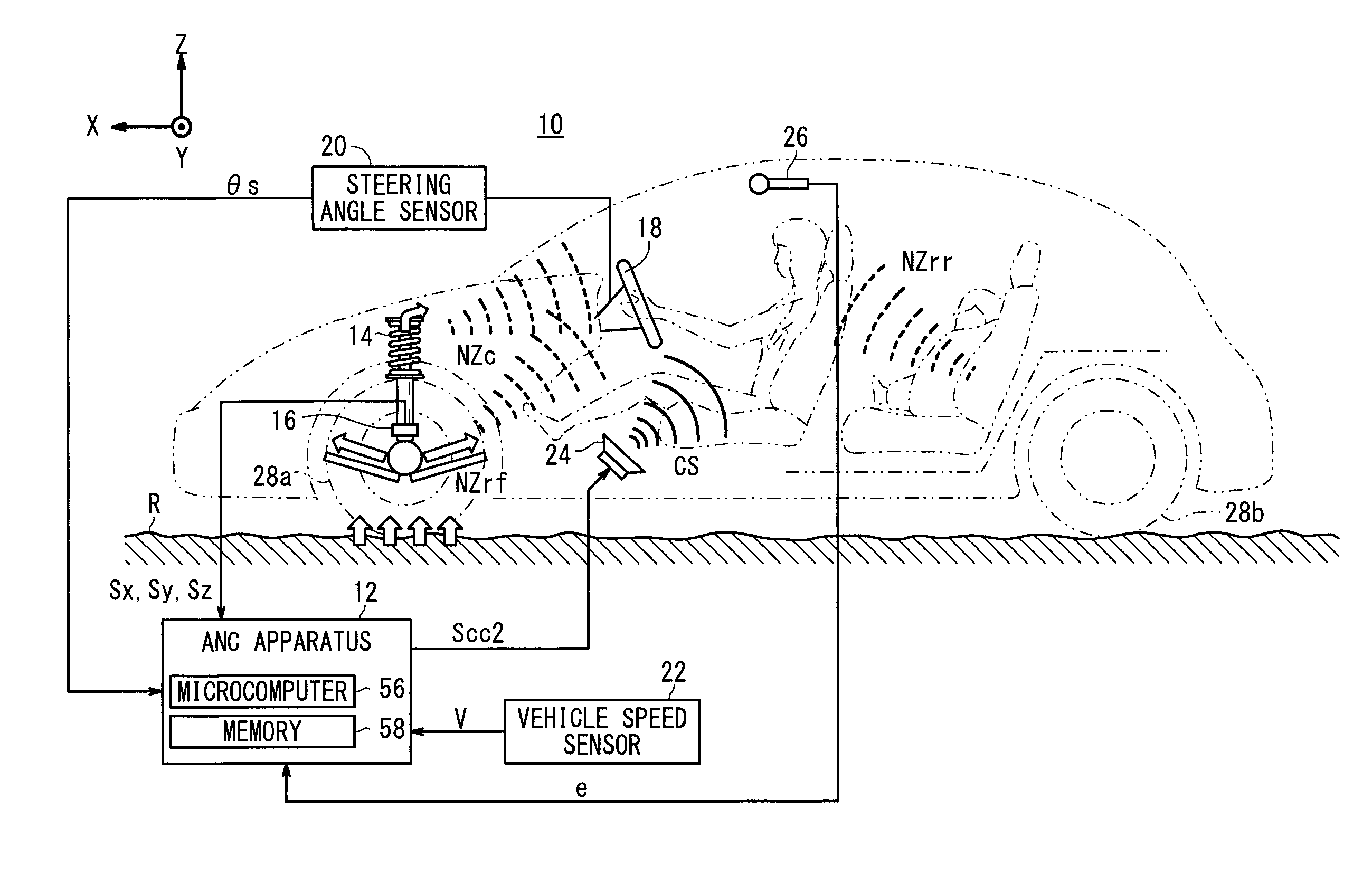
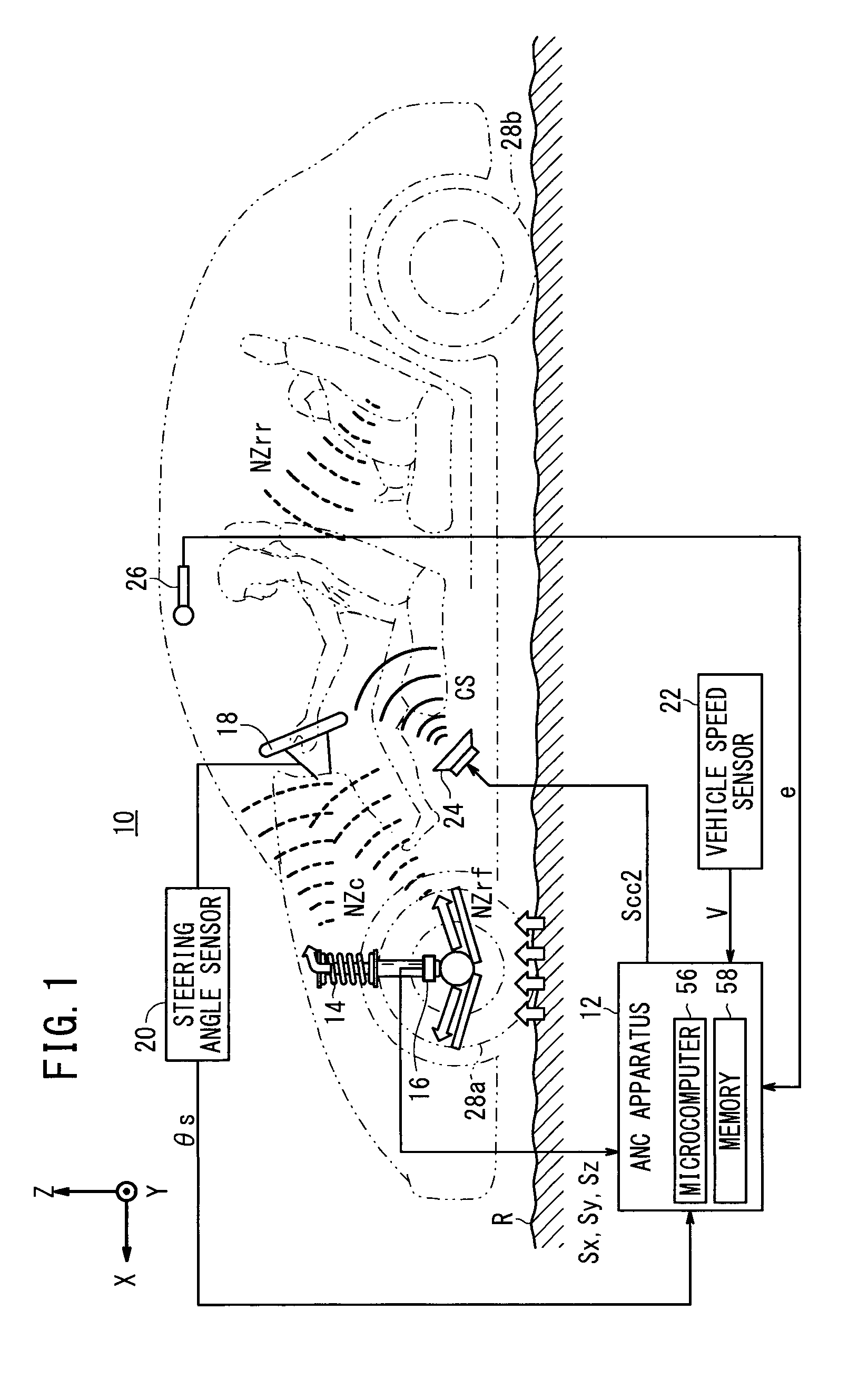
[0026]FIG. 1 is a schematic view of a vehicle 10 which incorporates an active noise control apparatus 12 (hereinafter referred to as “ANC apparatus 12”) according to an embodiment of the present invention. The vehicle 10 may be a vehicle such as a gasoline-powered vehicle, an electric vehicle (including a fuel cell vehicle), or the like.

[0027]The vehicle 10 includes, in addition to the ANC apparatus 12, a plurality of suspensions 14, a plurality of acceleration sensor units 16 combined respectively with the suspensions 14 that are coupled to front road wheels, a steering angle sensor 20 for detecting a steering angle θs [degrees] of a steering wheel 18, a vehicle speed sensor 22 for detecting a vehicle speed V [km / h] of the vehicle 10, a speaker 24, and a microphone 26. The steering angle θs represents the extent to which the steering wheel 18 is turned.

[0028]The ANC apparatus 12 generates a second combined cont...


PUM


Abstract

An ANC apparatus using so-called adaptive control is provided with a cancellation sound output means which outputs front wheel cancellation sound that cancels front wheel vibration noise due to front wheel vibration at a position to be silenced on the basis of a front wheel reference signal, and outputs rear wheel cancellation sound that cancels rear wheel vibration noise due to predicted rear wheel vibration at the position to be silenced on the basis of a rear wheel reference signal, and a turning state detection means which detects a turning state of a vehicle. When a difference in travel trajectory between a front wheel and a rear wheel is detected on the basis of the turning state, the cancellation sound output means suppresses the output of the rear wheel cancellation sound.

Description

CROSS-REFERENCE TO RELATED APPLICATIONS[0001]This application is a National Stage entry of International Application No. PCT / JP2011 / 071983, filed Sep. 27, 2011, which claims priority to Japanese Application No. 2010-284297, filed Dec. 21, 2010. The disclosures of the prior applications are hereby incorporated in their entirety by reference.TECHNICAL FIELD[0002]The present invention relates to an active vibration noise control apparatus for canceling a vibration noise based on a road input with a canceling sound, and more particularly to an active vibration noise control apparatus for canceling such a vibration noise according to a so-called adaptive control process.BACKGROUND ART[0003]Active noise control apparatus (hereinafter referred to as “ANC apparatus”) are known as apparatus for controlling acoustics in relation to a vibration noise in vehicular passenger compartments. General ANC apparatus reduce a vibration noise by outputting a canceling sound that is in opposite phase wit...

Claims


Application Information

Patent Timeline
Patent Type & Authority Patents(United States)
IPC IPC(8): G10K11/16H04B1/00G10K11/175G10K11/178
CPCG10K11/175G10K11/178G10K2210/12821G10K2210/3016G10K11/17823G10K11/17854G10K11/17883
Inventor SAKAMOTO, KOSUKEINOUE, TOSHIO
Owner HONDA MOTOR CO LTD
Why Eureka
Try Eureka