Self-diagnosis circuit

a self-diagnosis circuit and circuit technology, applied in the direction of electrical equipment, transmitter monitoring, transmission monitoring, etc., can solve the problems of difficult to quickly discover that an abnormality has occurred, difficult to detect an abnormality in the follower stage, and it is not possible to know of the occurrence of an abnormality. , to achieve the effect of easy to know

Active Publication Date: 2015-06-02
YOKOGAWA ELECTRIC CORP
View PDF6 Cites 0 Cited by
  • Summary
  • Abstract
  • Description
  • Claims
  • Application Information

AI Technical Summary

Benefits of technology

[0021]According to of some aspects of the present invention, by detecting the high-frequency signal that propagates along the signal transmission path from the output part toward the input part by the detector and by diagnosing for the existence of an abnormality in the follower stage of the high-frequency circuit according to the detection results of the detector (portion of the output part side from the coupling part of the self-diagnosis circuit with respect the signal transmission path), it is possible to enable diagnosis of an abnormality, not only in the previous stage included in the high-frequency circuit, but also in the follower stage thereof.
[0022]Also, according to the embodiment, a first pattern configured to function as an antenna that radiates the high-frequency signal propagating along the signal transmission path is formed on the signal transmission path and is provided in the detector, and when an abnormality is diagnosed, because the first pattern is used to send a notification signal, it is possible to easily know that an abnormality has occurred.

Problems solved by technology

For this reason, although it is possible to detect an abnormality in the previous stage included in the high-frequency circuit provided in a wireless communication apparatus, it is difficult to detect an abnormality in the follower stage.
However, wireless communication apparatuses are often installed in locations at a distance from the communication destination to which the communication is intended, and when a wireless communication apparatus is installed in an out-of-the way outdoor location, it is difficult to quickly discover that an abnormality has occurred.
In particular, in the above-described wireless field devices, because there are times when they are installed at distances as much as several hundred meters to several kilometers, unless patrols are frequently made to visit the wireless field devices, it is not possible to know of the occurrence of an abnormality.

Method used


Image

  • Self-diagnosis circuit
  • Self-diagnosis circuit
  • Self-diagnosis circuit

Examples


first embodiment

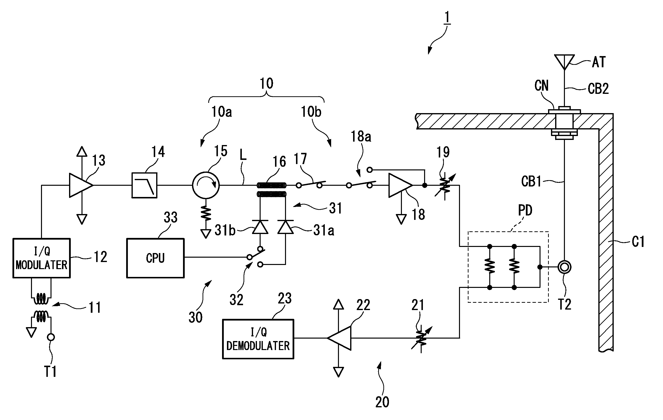
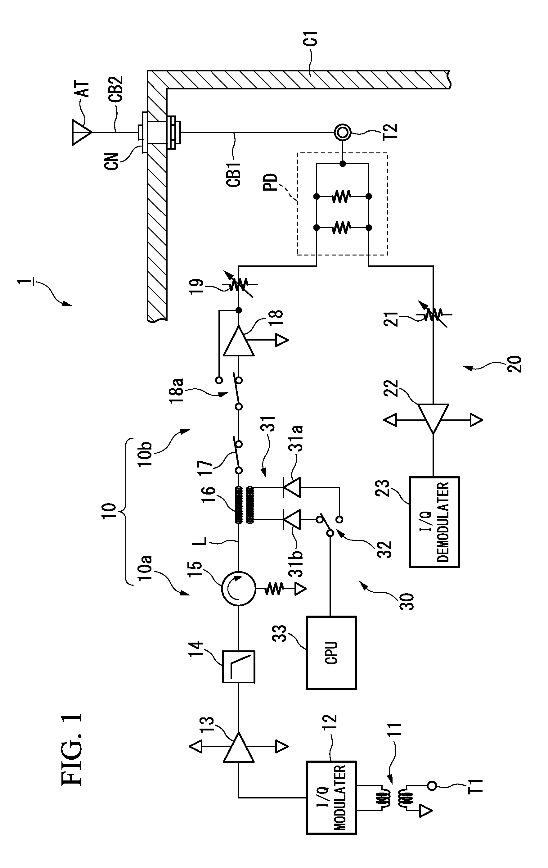
[0029]FIG. 1 is a block diagram showing the constitution of the main parts of a wireless communication apparatus having a self-diagnosis circuit according to the first embodiment of the present invention. As shown in FIG. 1, the wireless communication apparatus 1 of the present embodiment includes a transmitting circuit 10 (high-frequency circuit), a receiving circuit 20, a self-diagnosis circuit 30, a power divider PD, and an antenna AT (output part) and the like, wherein the signal (high-frequency signal) input from an input terminal T1 (input part) is transmitted as a wireless signal from the antenna AT, and receiving processing and the like is performed of a wireless signal received by the antenna AT.

[0030]The wireless communication apparatus 1 can diagnosis for an abnormality in the high-frequency circuit made of the transmitting circuit 10, the power divider PD, and the antenna AT and the like. If the diagnosis is that an abnormality exists, the wireless communication apparatu...

second embodiment

[0067]FIG. 3 is a block diagram showing the constitution of the main parts of a wireless communication apparatus having a self-diagnosis circuit according to the second embodiment of the present invention. In FIG. 3, blocks that are the same as those in FIG. 1 are assigned the same reference symbols. As shown in FIG. 3, a wireless communication apparatus 2 of the present embodiment has a detection element 24 (detection circuit) in the receiving circuit 20, and uses the result of the detection element 24 to detect the existence or non-existence of an abnormality in the circuit (high-frequency circuit) made up of the receiving circuit 20 and the circuitry that includes the power divider PD and the antenna AT (one part of the follower stage circuit 10b in the first embodiment).

[0068]The detection element 24 is a detection element similar to the detection elements 31a and 31b provided in the detector 31, and detects a signal input to the receiving circuit 20. Although the example shown ...

third embodiment

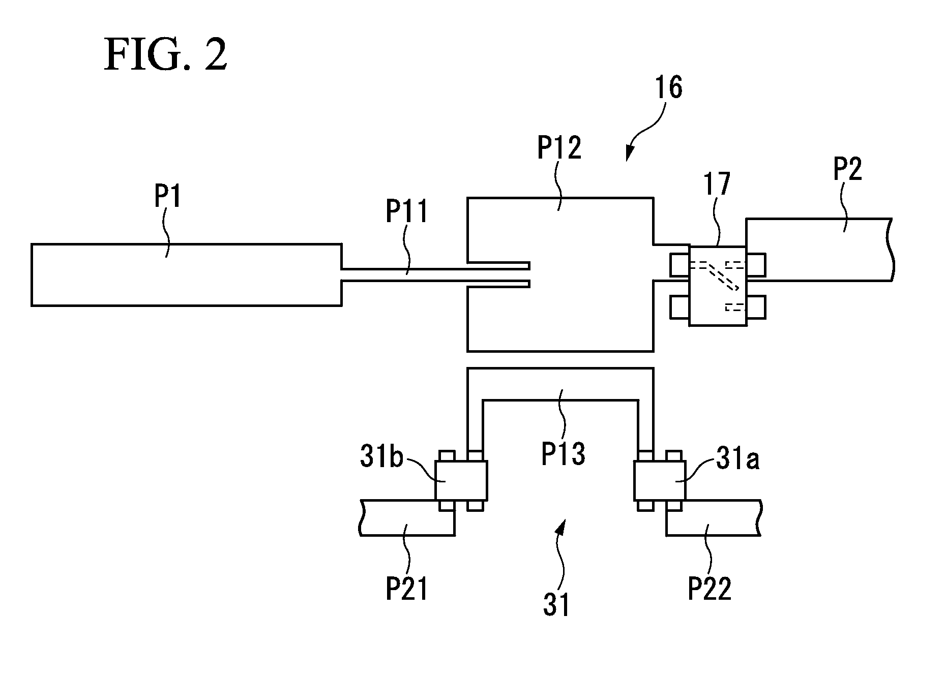
[0077]FIG. 4 is a plan view showing the constitution of the detector 31 in the third embodiment of the present invention. In FIG. 4, elements that are the same as shown in FIG. 2 are assigned the same reference symbols. The overall constitution of the wireless communication apparatus is the same as the overall constitution of the wireless communication apparatuses 1 and 2 shown in FIG. 1 or FIG. 3. As shown in FIG. 4, the detector 31 in the present embodiment has a CRLH (composite right-and-left-handed) transmission line P14 (third pattern), the electromagnetic coupling between the patterns P12 and P13 forming the bidirectional coupler 16 being varied, and the efficiency of radiating the notification signal from the pattern P12 that functions as a microstrip antenna being increased.

[0078]The CRLH transmission line P14 is a rectangular pattern formed on an inner layer or an outer layer of the board (for example, a multilayer board) on which the pattern P13 is formed in the condition ...


PUM


Abstract

A self-diagnosis circuit is coupled to a signal transmission path between a high-frequency signal input part and an output part and is configured to diagnose a high-frequency circuit using a signal that propagates along the signal transmission path. The self-diagnosis circuit includes a detector configured to detect the high-frequency signal propagating along the signal transmission path from the output part toward the input part; and a diagnosis unit that diagnoses for an abnormality in the follower stage of the high-frequency circuit disposed between a coupling part of the self-diagnosis circuit with respect to the signal transmission path and the output part, in accordance with the detection result of the detector.

Description

BACKGROUND OF THE INVENTION[0001]1. Field of the Invention[0002]The present invention relates to a self-diagnosis circuit that diagnoses for an abnormality in a high-frequency circuit.[0003]Priority is claimed on Japanese Patent Application No. 2012-102591, filed Apr. 27, 2012, the content of which is incorporated herein by reference.[0004]2. Description of the Related Art[0005]Wireless communication apparatuses have been commonly used in recent years in various fields because the wireless communication apparatuses have the advantages of not requiring the laying of communication lines, and can be easily installed in locations in which the laying of communication lines is difficult or the laying construction is uneconomical. For example, in plants and factories, on-site equipment (measuring instruments and actuators) capable of wireless communication and referred to as wireless field devices are used as the above-noted wireless communication apparatuses, with measurement signals indi...

Claims


Application Information

Patent Timeline
Patent Type & Authority Patents(United States)
IPC IPC(8): H04B17/00H04W24/00
CPCH04W24/00H04B17/17H04B17/19
Inventor MOCHIZUKI, SATOSHI
Owner YOKOGAWA ELECTRIC CORP
Why Eureka
Try Eureka