Magnetorheological fluid-based mount apparatus including rate dip track passage

a technology of magnetorheological fluid and mount apparatus, which is applied in the direction of mechanical apparatus, inertia effect dampers, shock absorbers, etc., can solve the problems of dynamic spring rate being undetectedly high at certain frequencies, sharp increase in and rise in dynamic stiffness, so as to reduce the dynamic stiffness of mount apparatus, increase the shear resistance of magnetorheological, and reduce the effect of dynamic stiffness

Active Publication Date: 2015-06-09
BEIJING WEST IND CO LTD
View PDF8 Cites 6 Cited by
  • Summary
  • Abstract
  • Description
  • Claims
  • Application Information

AI Technical Summary

Benefits of technology

[0011]The subject invention provides for such a magnetorheological fluid-based hydraulic mount apparatus like that disclosed in U.S. Pat. No. 6,622,995 and further incorporating a rate dip track passage defined by the partition assembly that extends between the pumping and receiving chambers and is radially spaced from the main fluid passage and the at least one electromagnet coil to define an upper track opening at the pumping chamber and a lower track opening at the receiving chambers for oscillating the magnetorheological fluid therethrough in response to the deformation of the flexible body and diaphragm to decrease the dynamic stiffness of the mount apparatus at a predetermined frequency. The mount apparatus further includes a controller for applying a current through the electromagnet coils in response to the signal from the sensor at the predetermined frequency and frequencies relatively close to and above the predetermined frequency for increasing the shear resistance of the magnetorheological fluid passing through the main fluid passage for substantially preventing the magnetorheological fluid from flowing through the main fluid passage to force the magnetorheological fluid to flow substantially only through the rate dip track passage for further decreasing the dynamic stiffness of the mount apparatus at the predetermined frequency and for preventing a sharp increase in the dynamic stiffness of the hydraulic mount apparatus from occurring at frequencies relatively close to and above the predetermined frequency.
[0012]Thus several advantages of one or more aspects of the invention are that a rate dip effect is created at the predetermined frequency (e.g. at idle frequency of an automotive vehicle), with the unwanted rate rise effect known in the prior art effectively eliminated at frequencies relatively close to and above the predetermined frequency because the path through which the magnetorheological fluid flows is controlled by the magnetorheological damping components of the system. Specifically, a relatively large current is applied to the at least one electromagnet coil at these frequencies, thereby substantially sealing the main fluid passage and forcing the fluid to only flow through the rate dip track passage, to provide for a larger rate dip effect and prevent the rate rise from occurring. Additionally, the greater density of the magnetorheological fluid in the mount of the invention as compared to the non-magnetorheological fluid in the mounts of the prior art provides for a greater rate dip effect.

Problems solved by technology

Due to the mass of the magnetorheological fluid in magnetorheological fluid-based damping mounts, it is known for the dynamic spring rate to be undesirably high at certain frequencies, like the idle frequency of automotive vehicles.
However, a known issue with such mounts is that a “rate rise” or sharp increase in dynamic stiffness of the mount occurs at vibration frequencies above the predetermined rate dip frequency because fluid flows through both the rate dip track passage and a primary fluid passage, causing an overlap of the frequencies that the two passages are effective at.

Method used


Image

  • Magnetorheological fluid-based mount apparatus including rate dip track passage
  • Magnetorheological fluid-based mount apparatus including rate dip track passage
  • Magnetorheological fluid-based mount apparatus including rate dip track passage

Examples


Embodiment Construction

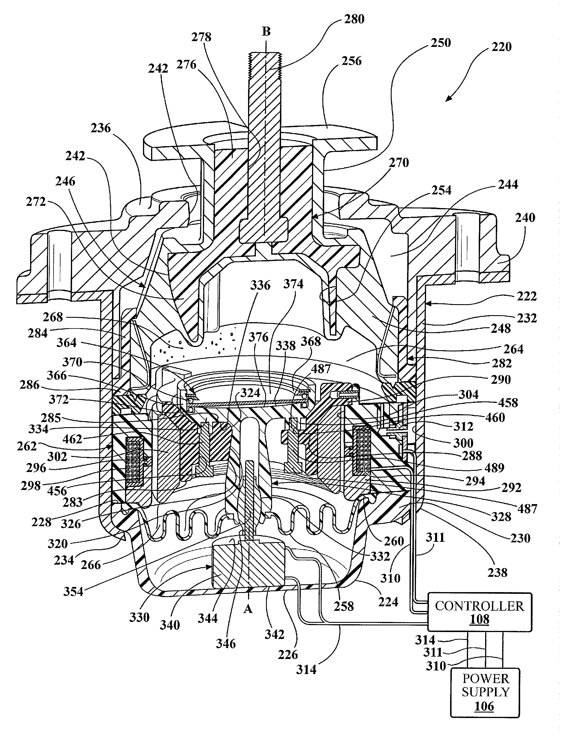
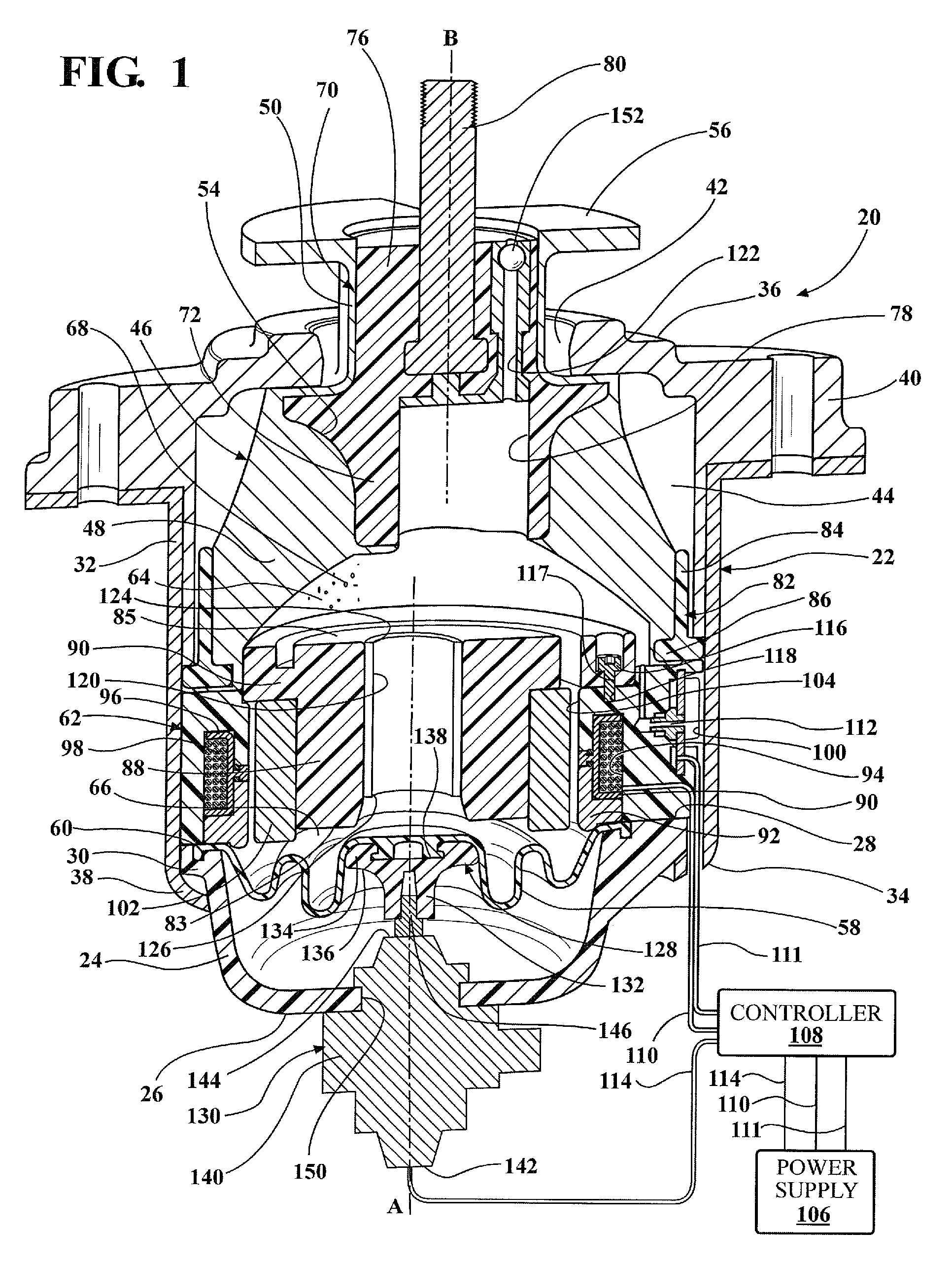
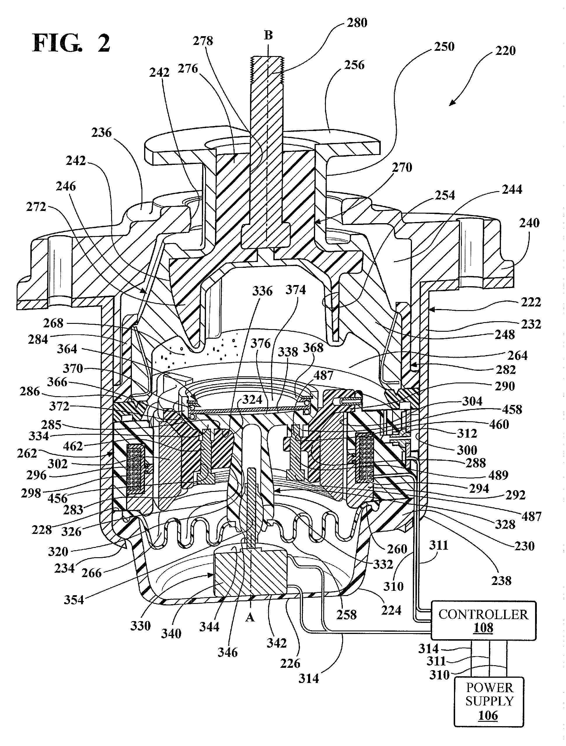
[0017]Referring to the Figures, wherein like numerals indicate corresponding parts throughout the several views, a hydraulic mount apparatus 20, 220 is generally shown for supporting a vibration source on a base. In the enabling embodiments, the hydraulic mount apparatus 20, 220 is used for supporting a component on the frame of an automotive vehicle. However, it should be appreciated that the mount apparatus 20, 220 could be used for supporting various other vibration sources on a base.

[0018]The hydraulic mount apparatus 20, 220 includes a housing 22, 222 that defines a housing chamber 44, 244 therein. The housing 22, 222 includes a generally bowl-shaped lower housing portion 24, 224 that extends about and along a first axis A from a closed lower housing portion lower end 26, 226 to an open lower housing portion upper end 28, 228. The lower housing portion 24, 224 defines a lower housing portion lip 30, 230 that extends radially outwardly from the lower housing portion upper end 28...


PUM


Abstract

A magnetorheological fluid-based hydraulic mount apparatus (20, 220) for supporting a vibration source on a base is disclosed. A main fluid passage (104, 304) extends between pumping chamber (64, 264) and receiving chamber (66, 266) for passing the fluid therebetween. Electromagnet coil (98, 298) variably generates a magnetic flux across the main fluid passage to variably change the damping stiffness of the mount. A rate dip track passage (120, 320) extends between the pumping chamber (64, 264) and receiving chamber (66, 266) for oscillating the magnetorheological fluid (68, 268) therethrough to decrease the dynamic stiffness of the mount apparatus (20, 220) at predetermined frequencies. A controller (108) applies a current through the electromagnet coils (98, 298) at the predetermined frequencies and frequencies relatively close to and above the redetermined frequencies for substantially preventing the magnetorheological fluid (68, 268) from flowing through the main fluid passage (104, 304) to force the magnetorheological fluid (68, 268) to flow substantially only through the rate dip track passage (120, 320) for preventing a sharp increase in the dynamic stiffness of the hydraulic mount apparatus (20, 220) from occurring at these frequencies.

Description

BACKGROUND OF THE INVENTION[0001]1. Field of the Invention[0002]A magnetorheological fluid-based hydraulic mount apparatus for supporting a vibration source on a base.[0003]2. Description of the Prior Art[0004]Conventional hydraulic mounts exist for supporting and providing vibration isolation of vibration sources. One well-known application of these mounts is for supporting components of automotive vehicles. These mounts typically operate to provide engine vibration isolation while also controlling the motion of the engine and connected powertrain components with respect to the vehicle frame or body structure. In many applications of engine and powertrain mounts, it is desirable to vary damping characteristics of the mount to provide selective isolation of vibrations at certain frequencies.[0005]Magnetorheological fluid-based vibration damping mounts have been developed to isolate or dampen vibrations at multiple frequencies. Magnetorheological fluid, as known in the art, is respon...

Claims


Application Information

Patent Timeline
Patent Type & Authority Patents(United States)
IPC IPC(8): F16F7/10F16F9/53F16F13/30F16F9/46F16F9/512
CPCF16F9/537F16F13/305F16F9/466F16F9/5126
Inventor SCHUMANN, ERIC LOUISBARTA, DAVID JOHNFOURMAN, BRENT WADESETTY, STEPHEN LEWIS
Owner BEIJING WEST IND CO LTD
Why Eureka
Try Eureka