Intelligent negative stiffness method and device avoiding bearing static loads
A technology of static load and negative stiffness, applied in non-rotational vibration suppression and other directions, can solve the problems of decreased system stiffness, reduced system stability, lack of generalizability, etc., and achieve the effect of low dynamic stiffness and high static stiffness
- Summary
- Abstract
- Description
- Claims
- Application Information
AI Technical Summary
Problems solved by technology
Method used
Image

Examples
Embodiment 1
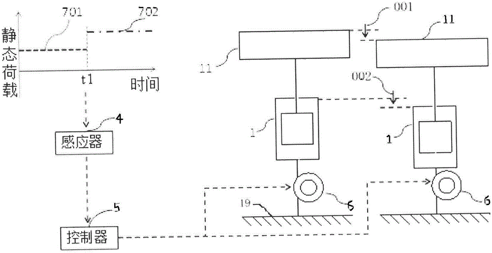
[0064] Attached figure 1 , An intelligent negative stiffness device that does not carry a static load. Its structure includes a passive negative stiffness element 1, a motor 6, a sensor 4 and a controller 5. The passive negative stiffness element 1 has a negative spring coefficient, and the negative stiffness of the passive negative stiffness element 1 The absolute value of the spring coefficient is not greater than the positive spring coefficient of the supporting external static load structure or sprung element 11.
[0065] The passive negative stiffness element 1 includes a mounting frame 18 and a passive negative stiffness element body. A deactivation element 3 is provided on the mounting frame 18. The passive negative rigidity element body is fixedly connected to the inside of the mounting frame 18, and the passive negative rigidity element body is provided with a transmission shaft 10, and the connection point between the transmission shaft 10 and the passive negative rigid...
Embodiment 2
[0072] Combine image 3 , An intelligent negative stiffness device that does not carry a static load. Its structure includes a passive negative stiffness element 1, a motor 6, a sensor 4 and a controller 5. The passive negative stiffness element 1 has a negative spring coefficient, and the negative stiffness of the passive negative stiffness element 1 The absolute value of the spring constant is not greater than the positive spring constant of the external static load bearing structure or the sprung element 11.
[0073] The passive negative stiffness element 1 includes a mounting frame 18 and a passive negative stiffness element body. A deactivation element 3 is provided on the mounting frame 18. The passive negative rigidity element body is fixedly connected to the inside of the mounting frame 18, and the passive negative rigidity element body is provided with a transmission shaft 10, and the connection point between the transmission shaft 10 and the passive negative rigidity el...
Embodiment 3
[0080] Based on the structure of the second embodiment above, refer to Figure 13 , The vehicle is simulated as a commonly used 1 / 4 vehicle dual-degree-of-freedom system, and the device of the present invention is installed in the vehicle suspension so that it is arranged in parallel with the vehicle’s suspension system, then the external static load structure or spring The upper element 11 is the vehicle body 15 and the unsprung element is the vehicle chassis 13. Vehicle tires 14 are installed under the vehicle chassis 13. A vibration reducing support spring 12 and a passive damper 16 are installed between the vehicle chassis 13 and the vehicle body 15.
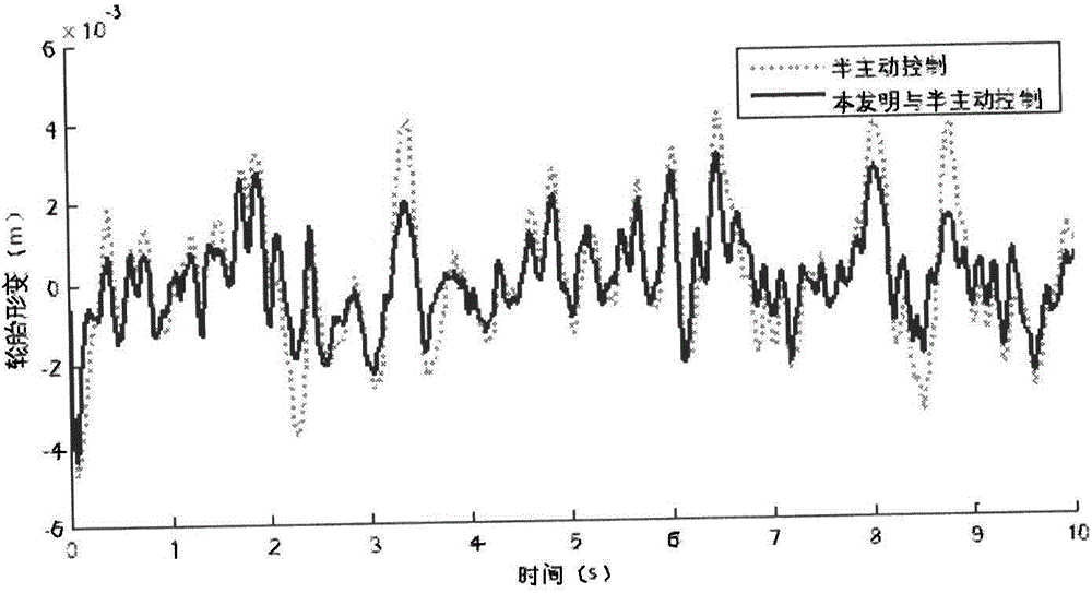
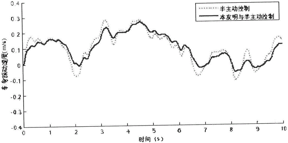
[0081] The relevant parameters are: the mass of the body 15 is 504.5kg, the mass of the vehicle chassis 13 and the vehicle tire 15 are 62kg, the stiffness of the suspension bearing spring is 13.1kN / m, the stiffness coefficient between the vehicle chassis 13 and the ground is 252kN / m, input excitation Is speed white noise. When ...
PUM
 Abstract
Description
Claims
Application Information
 - R&D
- Intellectual Property
- Life Sciences
- Materials
- Tech Scout
- Unparalleled Data Quality
- Higher Quality Content
- 60% Fewer Hallucinations
Browse by: Latest US Patents, China's latest patents, Technical Efficacy Thesaurus, Application Domain, Technology Topic, Popular Technical Reports.
© 2025 PatSnap. All rights reserved.Legal|Privacy policy|Modern Slavery Act Transparency Statement|Sitemap|About US| Contact US: help@patsnap.com