Compound control method and system for hydraulic drive unit position control system

A technology of drive unit and control system, which is applied in the directions of fluid pressure actuation system components, fluid pressure actuation devices, program control manipulators, etc., can solve the lack of engineering practicability, the lack of pertinence of dynamic stiffness control compensation, and the complex control method. and other problems, to achieve the effect of simple algorithm, improved robustness, improved accuracy and robustness

Active Publication Date: 2019-07-19
江苏亚力亚气动液压成套设备有限公司
View PDF5 Cites 6 Cited by
  • Summary
  • Abstract
  • Description
  • Claims
  • Application Information

AI Technical Summary

Problems solved by technology

Although these methods have good control effects, the control methods are relatively complicated and lack engineering practicability.
More importantly, the above position control method fails to propose and grasp the inherent dynamic stiffness of the position control system of the hydraulic drive unit. Therefore, when the position control system of the hydraulic drive unit is used as the control inner loop, its corresponding controller cannot use the hydraulic drive unit Its own dynamic stiffness is the starting point, which leads to a slight lack of pertinence in its dynamic stiffness control compensation

Method used


Image

  • Compound control method and system for hydraulic drive unit position control system
  • Compound control method and system for hydraulic drive unit position control system
  • Compound control method and system for hydraulic drive unit position control system

Examples


Embodiment 1

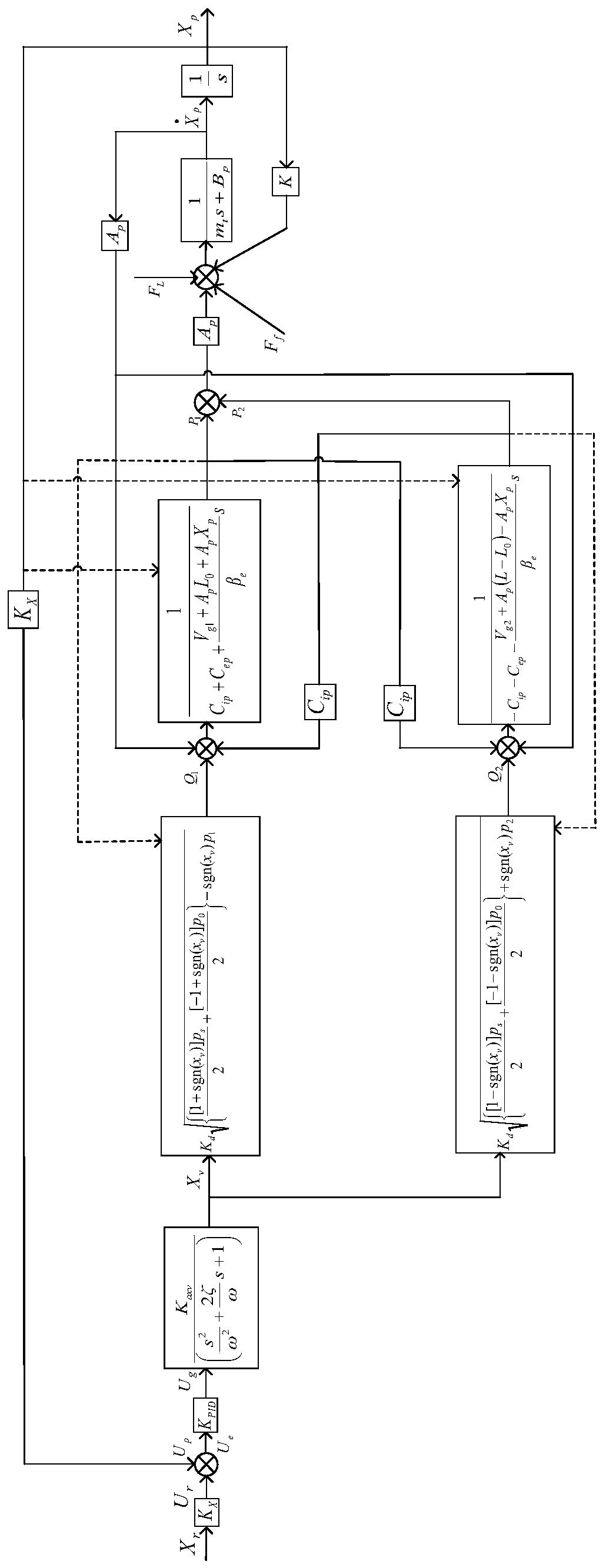
[0046] figure 2 It is a block diagram of the transfer function model of the existing hydraulic drive unit position control system for the composite control method of the hydraulic drive unit position control system according to the embodiment of the present application. The existing hydraulic drive unit (inner ring) position control system includes: system input module 1, position controller 2, hydraulic drive unit 3, and feedback control module 4, figure 2 The transfer functions of the various components of the existing position control system are shown. Among them, the system input module 1 is used to obtain the given voltage input signal (system input signal) of the position control system and the voltage signal (actual output signal) corresponding to the current system output position signal detected by the displacement sensor 11, and obtain the deviation. The position controller 2 obtains the above-mentioned deviation input signal from the system input module 1, and p...

Embodiment 2

[0093] In the actual application process, due to the simplification and neglect steps in the construction process of the feedforward compensation model and the adaptive feedforward compensation model, only the feedforward compensation control and the adaptive feedforward compensation control can make the hydraulic drive unit receive The stiffness after the external load force is improved, but it may not be possible to fully make the hydraulic drive unit stiffness reach the infinite target state.

[0094] Therefore, in order to further improve the effect of the feedforward compensation control and the adaptive feedforward compensation control in the first embodiment above, a self-tuning position control is designed on the basis of the feedforward compensation control and the adaptive feedforward compensation control method, this method is used to control the forward channel gain of the online control system, and further increase the inherent dynamic stiffness of the position con...

Embodiment 3

[0106] In addition, based on the composite control method in Embodiment 1 of the present invention, the present invention also proposes a composite control system for the position control system of the hydraulic drive unit, which is used to realize the above-mentioned composite control method. Figure 10 It is a structural schematic diagram of a compound control system used for a position control system of a hydraulic drive unit according to an embodiment of the present application. Such as Figure 10 As shown, the above compound control system includes: a system input module 1 , a position controller 2 , a hydraulic drive unit 3 , a feedforward compensation controller 5 , an adaptive feedforward compensation controller 6 and a feedback control module 4 .

[0107] Among them, the system input module 1, which is implemented according to the above step S110, is configured as the current actual output signal and the system input signal, and obtains a deviation input signal repres...


PUM


Abstract

The invention discloses a compound control method and system for a hydraulic drive unit position control system. The method comprises the steps that feedforward compensation control is adopted for forming a stiffness model opposite to first inherent dynamic stiffness in the system for compensating the influence of external load force on the inherent dynamic stiffness from the load force application point to the system output end. Further, self-adaptive feedforward compensation control is added for further compensating the deviation of input voltage and output voltage, and thus variations in system load pressure are compensated. In addition, through self-adjusting position control, the robustness of the two feedforward compensation control modes is improved. Finally, the three compensationcontrol modes are integrated, and the position compound control method is formed, so that the system dynamic stiffness tends to infinite. The dynamic stiffness of the position control system is improved, and the precision and robustness of outer loop compliant control are improved. Besides, the algorithm of the method is simpler and easier to implement in engineering.

Description

technical field [0001] The invention relates to the field of fluid transmission and control, in particular to a composite control method and system based on dynamic stiffness compensation for a position control system of a hydraulic drive unit of a legged robot. Background technique [0002] The hydraulically driven legged robot has a certain adaptability to unknown and uneven ground environments, and can well achieve obstacle-crossing functions, and is widely used in field detection, rescue, military and other fields. The hydraulically driven quadruped robot Big-Dog developed by Boston Corporation in the United States is an example. This robot is modeled on the limb structure of common quadruped mammals, and can have good motion performance in complex environments such as grassland, jungle, beach, swamp, and snow. , and can carry heavy objects. The above studies have enhanced the practical value of robots and prompted researchers from various countries to conduct research ...

Claims


Application Information

Patent Timeline
Patent Type & Authority Applications(China)
IPC IPC(8): F15B21/08B25J9/16
CPCB25J9/16B25J9/1602F15B21/087F15B2211/6656F15B2211/765
Inventor 巴凯先俞滨刘瑞栋娄文韬高正杰马国梁
Owner 江苏亚力亚气动液压成套设备有限公司
Why Eureka
Try Eureka