Double-stator axial magnetic flow arc-shaped permanent magnet motor

A permanent magnet motor, axial magnetic flux technology, applied in the direction of magnetic circuit shape/style/structure, electrical components, electromechanical devices, etc., can solve the problems of system vibration, poor dynamic stiffness, slow motion response, etc., and achieve high dynamic stiffness. , the effect of reducing the volume and weight, and improving the response speed

Active Publication Date: 2014-02-12
BEIJING INSTITUTE OF TECHNOLOGYGY
View PDF3 Cites 7 Cited by
  • Summary
  • Abstract
  • Description
  • Claims
  • Application Information

AI Technical Summary

Problems solved by technology

[0003] The purpose of the present invention is to solve the problems of system vibration, slow motion response and poor dynamic stiffness caused by the indirect drive mode composed of "high-speed servo motor + gear set + ring gear" in the existing scanning servo mechanism, and provide A dual-stator axial flux arc permanent magnet motor

Method used


Image

  • Double-stator axial magnetic flow arc-shaped permanent magnet motor
  • Double-stator axial magnetic flow arc-shaped permanent magnet motor
  • Double-stator axial magnetic flow arc-shaped permanent magnet motor

Examples


specific Embodiment approach 1

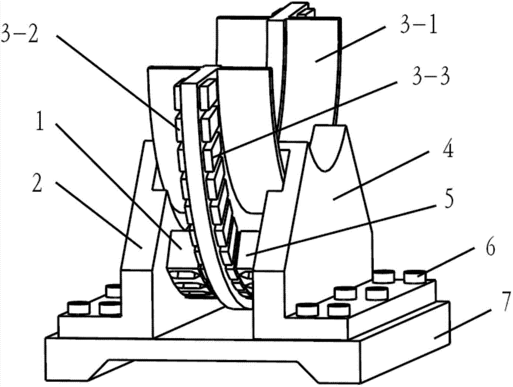
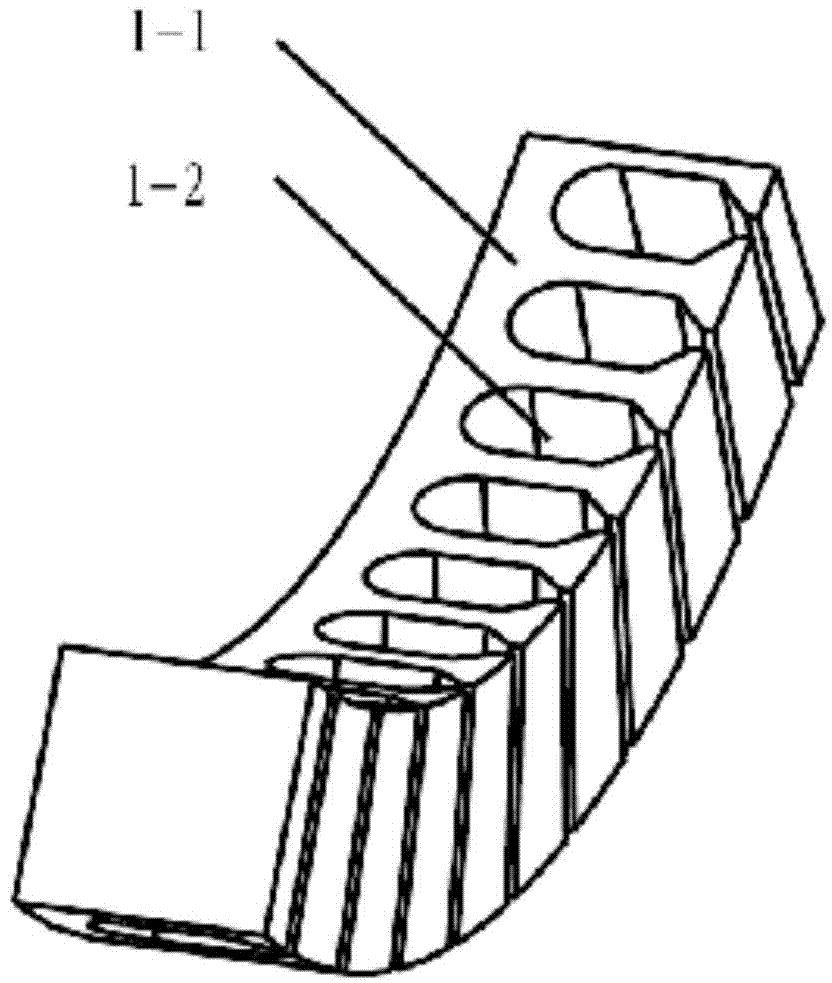
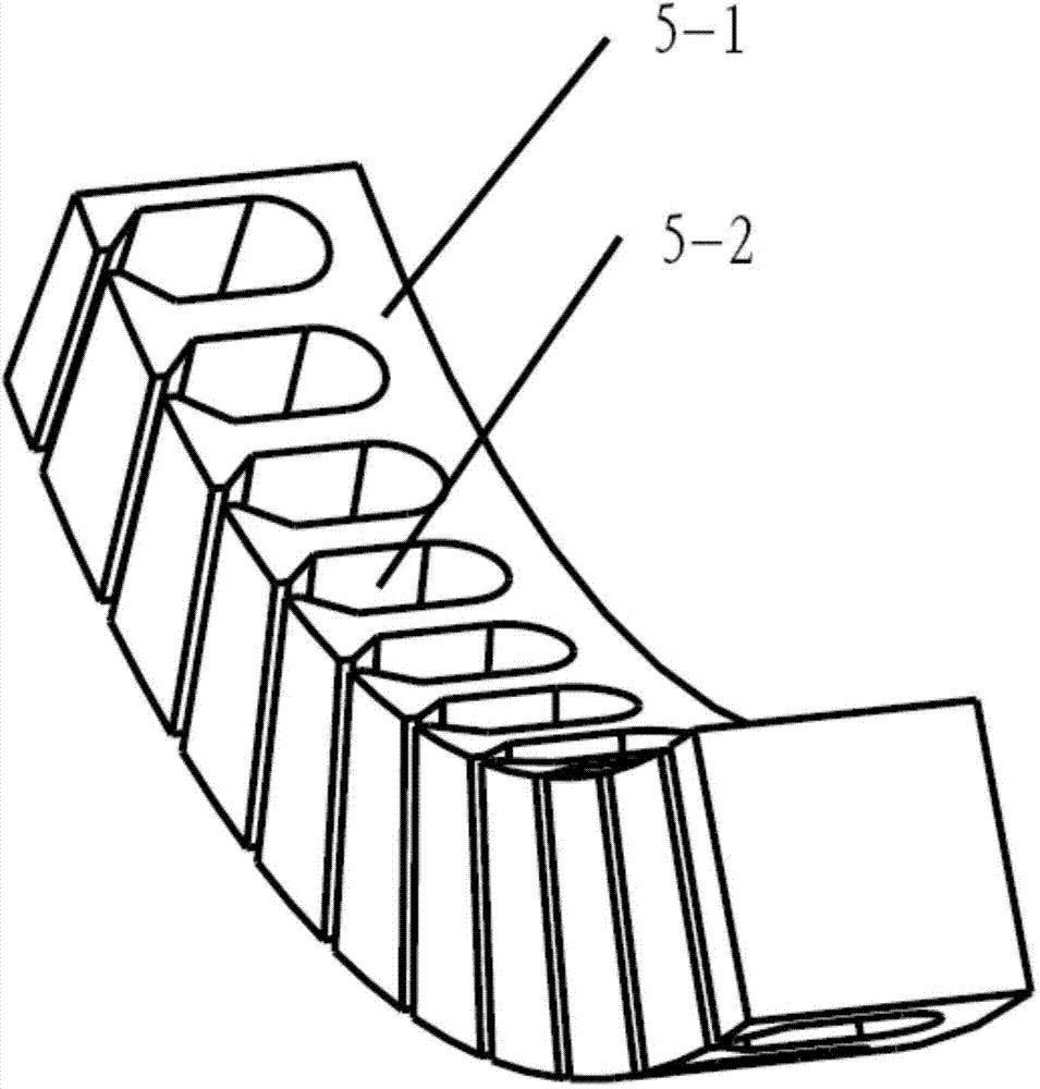
[0018] Specific implementation mode one: combine Figure 1 to Figure 8 Describe this embodiment. This embodiment includes a left side arc stator 1, a left support bracket 2, an arc rotor core 3-1, a left permanent magnet 3-2, a right permanent magnet 3-3, and a right support Bracket 4, right side arc-shaped stator 5, fastening screw 6 and base 7; the section of the arc-shaped rotor core 3-1 is T-shaped, and the arc-shaped rotor core 3-1 includes a supporting part 3-1 -1 and effective working part 3-1-2; arc rotor iron core 3-1, left permanent magnet 3-2 and right permanent magnet 3-3 form arc rotor, wherein the left permanent magnet 3-2 The N and S poles are alternately arranged on the left side of the arc-shaped rotor core 3-1, and the N and S poles of the right permanent magnet 3-3 are alternately arranged on the right side of the arc-shaped rotor iron core 3-1; the left side of the arc-shaped stator 1 Located on the left side of the rotor, the right arc-shaped stator 5 is ...

specific Embodiment approach 2

[0019] Specific implementation mode two: combination figure 1 , figure 2 , image 3 , Figure 4 , Image 6 , Figure 7 , Figure 8 with Figure 9 This embodiment is different from Embodiment 1 in that the permanent magnets are arranged as a series magnetic circuit, and the polarities of the permanent magnets are different at the opposite sides of the arc-shaped rotor core. When the N pole on the left side faces the arc-shaped rotor core 3-1, the right side is the S pole facing the arc-shaped rotor core 3-1, and when the left side is the S pole facing the arc-shaped rotor core 3-1, the right side is the N pole facing the arc-shaped rotor core 3-1, and the two sides The N and S poles are arranged alternately.

Embodiment approach 3

[0020] Embodiment 3: The difference from Embodiment 1 or Embodiment 2 is that the arc of the arc-shaped rotor is larger than that of the stator, and the arc length of the arc-shaped rotor can be designed according to the requirements of the operating angle.


PUM


Abstract

The invention relates to a double-stator axial magnetic flow arc-shaped permanent magnet motor, and belongs to the technical field of limited angle permanent magnet motors. A rotor is composed of an arc-shaped rotor iron core and permanent magnets, wherein the permanent magnets are installed on the left side and the right side of the arc-shaped rotor iron core. A double-stator assembly is composed of a left-side arc-shaped stator located at the left side of the arc-shaped rotor and a right-side stator located on the right side of the rotor. The left-side arc-shaped stator, the arc-shaped rotor iron core and the permanent magnet on the left side form a left-side axial magnetic flow arc-shaped permanent magnet motor body, the right-side arc-shaped stator, the arc-shaped rotor iron core and the permanent magnet on the right side form a right-side axial magnetic flow arc-shaped permanent magnet motor body, the torque of the two arc-shaped permanent magnet motor bodies is overlaid to serve as the output torque of the whole motor, the power density and the torque density of the motor are improved, the direct drive mode is adopted for a scanning structure, and the problems that the indirect drive mode formed by a high-speed servo motor, a gear set, a gear ring and the like in an existing scanning mechanism causes system vibration, slow motion response, poor dynamic stiffness and the like are solved.

Description

technical field [0001] The invention relates to a double-stator axial flux arc permanent magnet motor, which belongs to the technical field of motors, in particular to a double stator axial flux arc permanent magnet motor which moves within a limited rotation angle. Background technique [0002] The existing scanning servo mechanism mostly adopts the indirect drive mode consisting of "high-speed servo motor + gear set + ring gear". This transmission structure through gear meshing inevitably has nonlinear friction, interval dead zone and elastic deformation. , when completing motions such as starting, accelerating, decelerating, reversing, and braking, it is easy to cause system vibration, slow motion response, and poor dynamic stiffness. These inherent defects make the scanning mechanism further improve its speed regulation performance and positioning capabilities. Difficult to achieve technical breakthroughs. The method of direct drive by arc-shaped torque motor can effect...

Claims


Application Information

Patent Timeline
Patent Type & Authority Applications(China)
IPC IPC(8): H02K16/04H02K1/27
Inventor 赵静户恒在刘向东陈振
Owner BEIJING INSTITUTE OF TECHNOLOGYGY
Why Eureka
Try Eureka