Pivoting latch for cable housing

a technology of latch arrangement and cable housing, which is applied in the direction of optical elements, coupling device connections, instruments, etc., can solve the problems of difficult installation and expensive multi-component conventional cable housings such as those including pull tabs, and the single-piece flexible flat plate-metal latch is difficult to press and can sometimes unlatch easily. , to achieve the effect of reducing the range of motion, and reducing the number of screws

Active Publication Date: 2015-06-09
SAMTEC
View PDF16 Cites 12 Cited by
  • Summary
  • Abstract
  • Description
  • Claims
  • Application Information

AI Technical Summary

Benefits of technology

[0008]To overcome the problems described above, preferred embodiments of the present invention provide a plug housing with a superior latch, in which a pivot point of the latch is shifted forward, while the actuation point is shifted toward the back of the plug housing. Shifting the pivot point forward provides a latch with a smaller range of motion and greater precision. In addition, shifting the actuation point back gives a greater mechanical moment to the arms of the latch, a lower required actuation force, and a more convenient location to grasp and actuate the latch. Moving the structure of the locking portion, spring, and actuation members of the latch towards outer side walls of the plug housing more evenly distributes forces and provides a stronger beam design for a mechanical moment arm of the latch.

Problems solved by technology

However, the above described conventional cable housings suffer from various deficiencies.
The multi-component conventional cable housings such as those including a pull tab are difficult to install and are expensive because of the large number of parts used therein.
The single-piece flexible-flat-plate-metal latches are hard to press and can sometimes unlatch easily.
Not only that, but the screws, rivets, etc. used to mount the single-piece flexible-flat-plate-metal latches to the conventional cable housings penetrate into the conventional cable housings, reducing the total amount of room available for other components to be provided within the conventional cable housings.

Method used


Image

  • Pivoting latch for cable housing
  • Pivoting latch for cable housing
  • Pivoting latch for cable housing

Examples


Embodiment Construction

[0038]Preferred embodiments of the present invention will be described in detail with reference to the accompanying drawings. The following description is in all aspects illustrative and not restrictive, and should not be construed to restrict the applications or uses of the various preferred embodiments of the present invention in any manner.

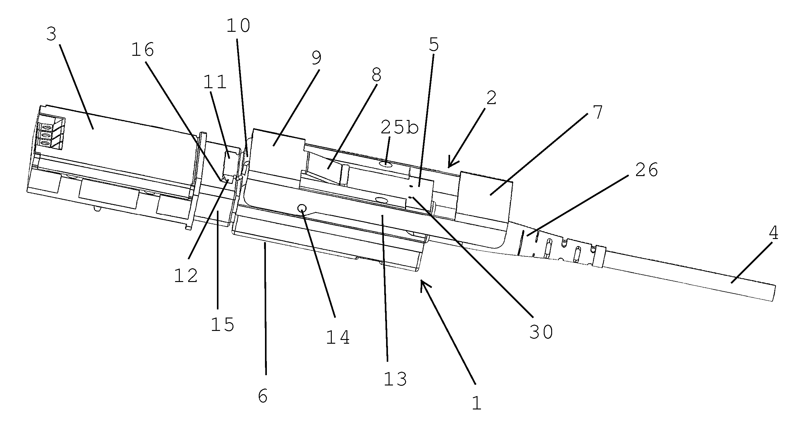
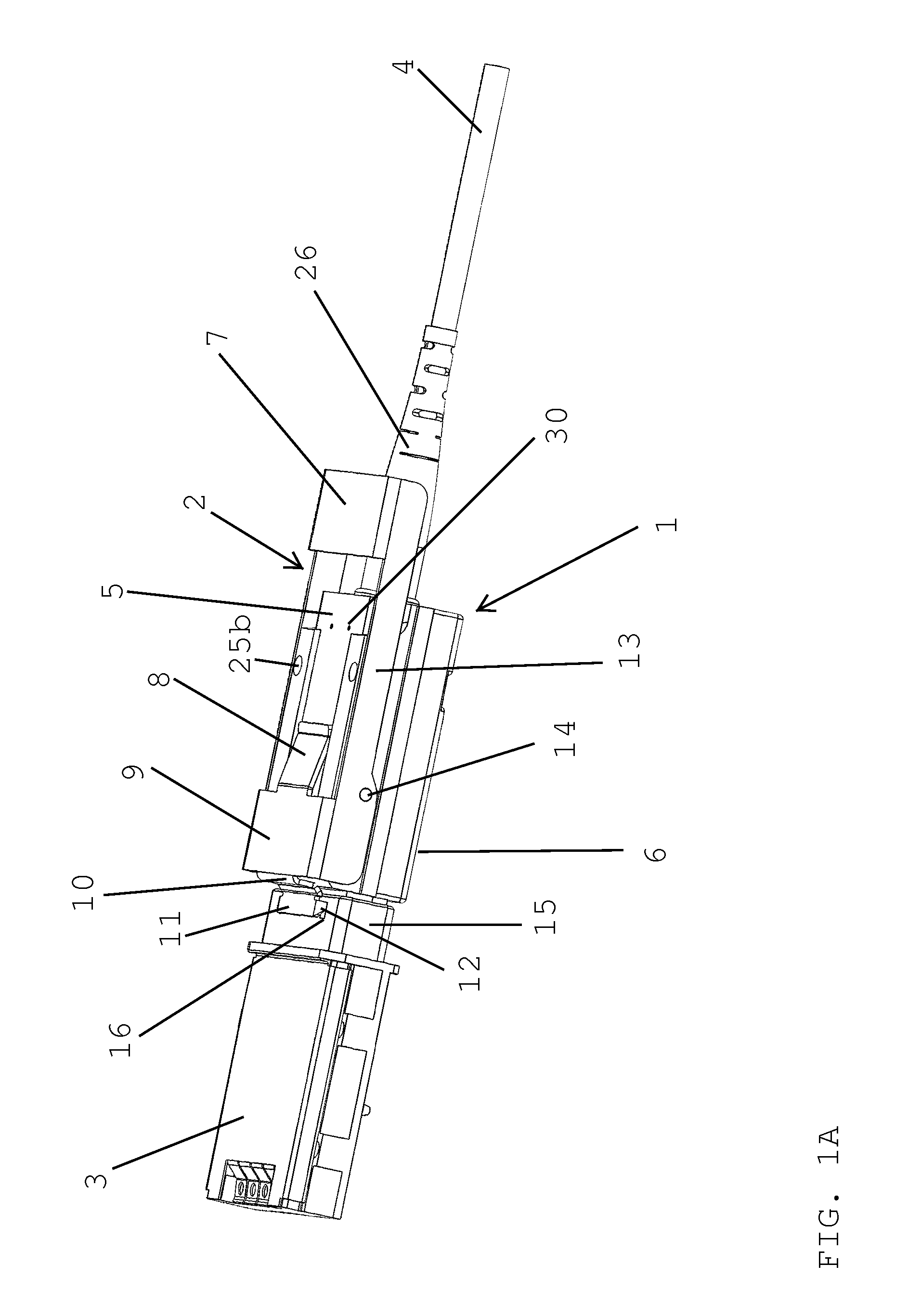
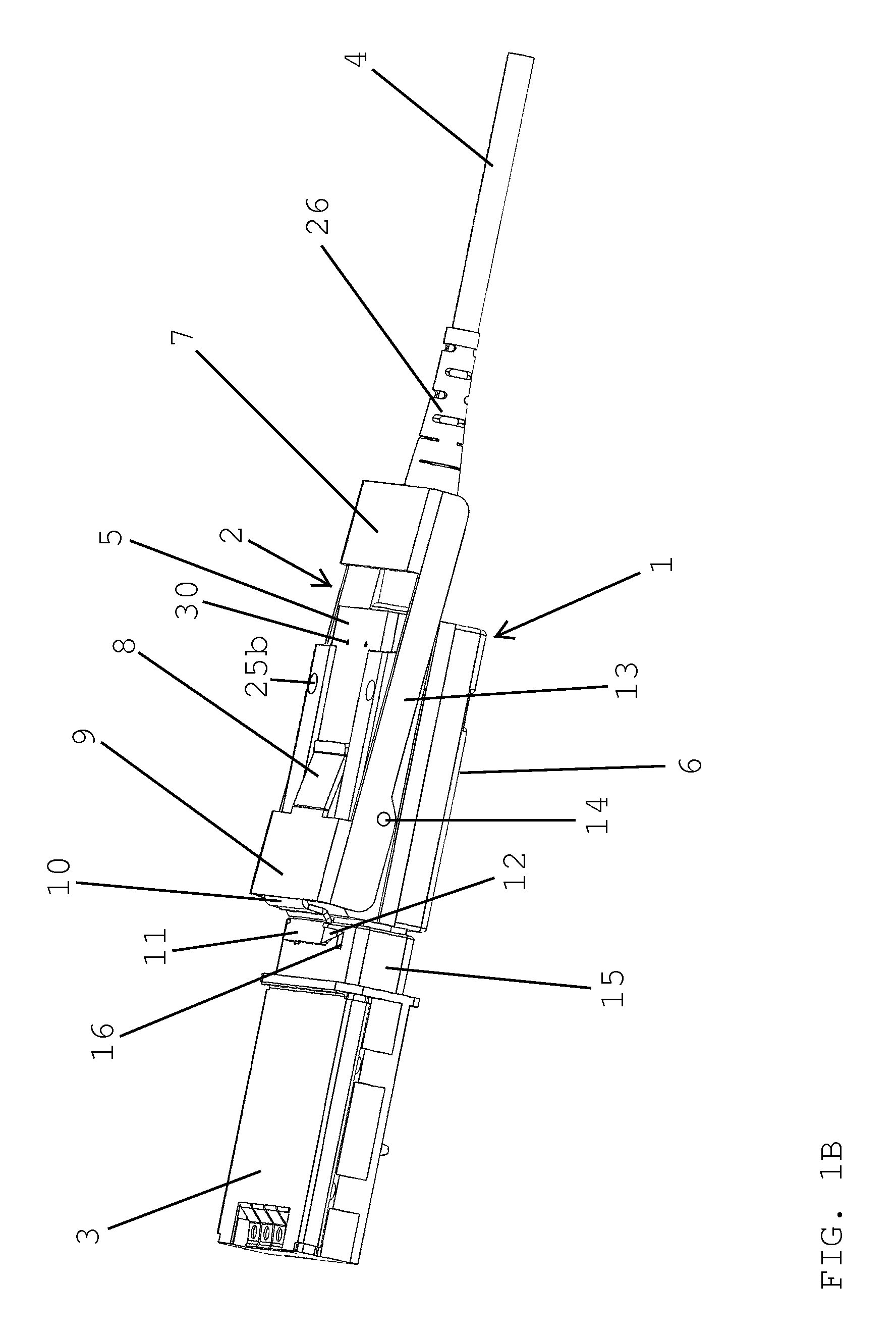
[0039]FIGS. 1A and 1B show a preferred embodiment of a plug housing 1 in accordance with a preferred embodiment of the present invention. The plug housing 1 preferably includes an upper half 5 and a lower half 6 which are connected together through the use of, for example, rivets. The upper half 5 and the lower half 6 are preferably formed through, for example, die casting. However, it is also possible to form the upper half 5 and the lower half 6 through machining, stamping, molding (plastic or metal molding), casting, etc., if so desired. The upper half 5 is preferably arranged to support a latch 2. The plug housing 1 is arranged such that it...


PUM


Abstract

A plug housing preferably includes an upper housing and a lower housing defining a cavity and a latch portion arranged to be pivotable about the plug housing and including a pair of actuator beams. Respective ones of the pair of actuator beams are preferably arranged to be directly opposed to respective side surfaces of the plug housing. The latch portion is preferably arranged to be connected to the upper housing and the lower housing through a pair of projection portions or a pair of pivot holes arranged on opposite ones of the pair of actuator beams of the latch portion. The latch portion is preferably pivotable about the plug housing at a position corresponding to the pair of projection portions or the pair of pivot holes. The latch preferably includes a catch mechanism and a spring mechanism connected to a forward plate without contacting the pair of actuator beams.

Description

BACKGROUND OF THE INVENTION[0001]1. Field of the Invention[0002]The present invention relates to a cable housing. More specifically, the present invention relates to a cable housing including a pivoting latch arrangement.[0003]2. Description of the Related Art[0004]Cable housings arranged to connect optical or electrical cables to receiving receptacles are well known in the art. In such arrangements, it is necessary to releasably connect the cable housings to the receiving receptacles in a manner that is both firm and secure. Conventional arrangements that have been tried in the art include cable housings which include latches arranged to slide in and out of receiving notches on the receiving receptacle. Such latches typically include actuators with a pull tab that moves the latch such that the latch will slide in and out of the notches on the receiving receptacle and screws, rivets, and / or other fasteners arranged to fix the latches to the cable housing in a manner that permits the...

Claims


Application Information

Patent Timeline
Patent Type & Authority Patents(United States)
IPC IPC(8): H01R13/62G02B6/38H01R13/629G02B6/42
CPCG02B6/3897H01R13/62933G02B6/4278H01R13/629G02B6/3888
Inventor SCHMELZ, DALE FRANCISFAITH, CHADRICK PAULOUYANG, WILLIAM CHIENG
Owner SAMTEC
Why Eureka
Try Eureka