Turnover device of solar battery assembly

A technology of solar cells and flipping devices, which is applied in the direction of electrical components, circuits, semiconductor devices, etc., can solve the problems of low automation integration, increased probability of machine breakage, and poor compatibility, so as to improve automation integration, avoid pollution and broken, The effect of short action time

Inactive Publication Date: 2011-10-05
SHANGHAI WEISONG IND AUTOMATION
View PDF3 Cites 10 Cited by
  • Summary
  • Abstract
  • Description
  • Claims
  • Application Information

AI Technical Summary

Problems solved by technology

[0003] 1. Manual flipping wastes manpower and is inefficient, and the speed of manual operation cannot meet the requirements of mass production
[0004] 2. There is too much contact with the cells in manual flipping, and a certain degree of pollution is formed on the surface of the cells during the flipping process
[0005] 3. The traditional turning mechanism occupies a large space and has a low degree of automation integration
[0006] 4. The traditional turning mechanism can only correspond to a solar cell module of a specified size, and the compatibility is poor
[0007] 5. At present, solar cells have a very obvious tendency to become lighter and thinner. At the same time, the cells in some stations have obvious bending deformation, while the traditional turning mechanism has a large range of motion, and the cells will be damaged during the turning process. Common The damage includes hidden chipping, missing corners, crushing, sticking, chipping, etc. As the thickness of the cell becomes thinner, the probability of machine chipping will increase sharply

Method used


Image

  • Turnover device of solar battery assembly
  • Turnover device of solar battery assembly
  • Turnover device of solar battery assembly

Examples


Embodiment

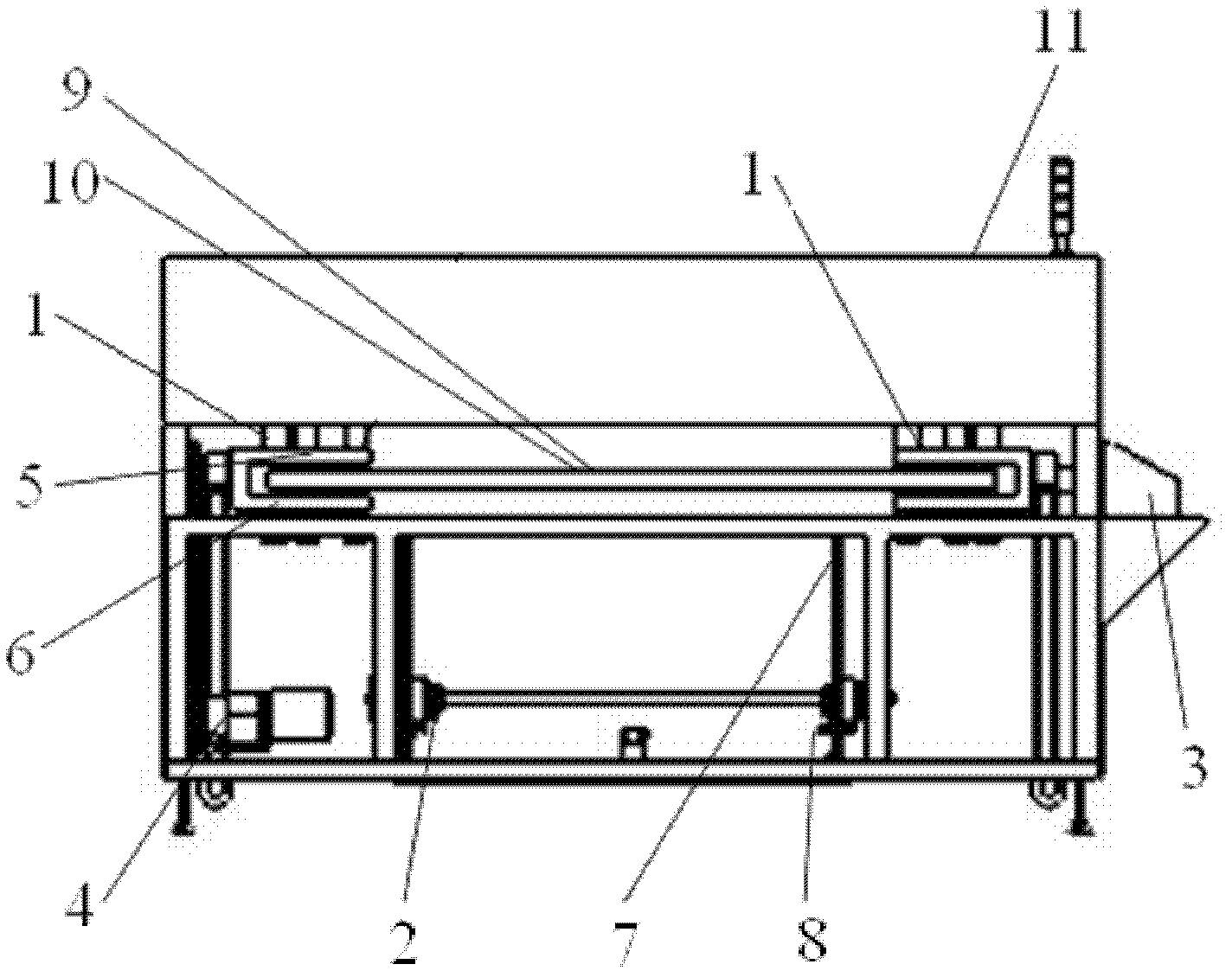
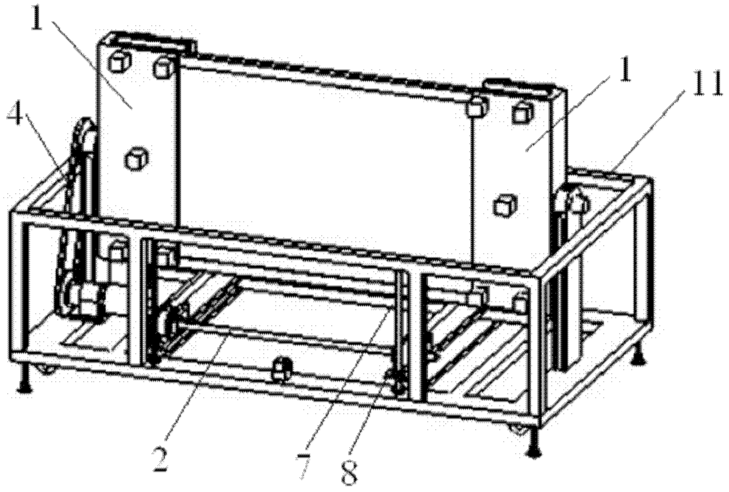
[0025] A flipping device for a solar cell module, the structure of which is as follows Figure 1~2 As shown, the overturning device includes a clamping overturning mechanism 1, a conveyor belt lifting mechanism 2, a control system 3, a sprocket drive mechanism 4, an upper limit position sensor 7, a lower limit position sensor 8, and a protective outer frame 11. The clamping overturning mechanism 1 is two Two semi-frame structures are respectively arranged on both sides of the device to form a holder for holding solar cell modules. A first clamping sensor 5 and a second clamping sensor 6 are installed on the inner side of the clamping turning mechanism 1 , and a first component judging sensor 9 and a second component judging sensor 10 are installed on the outer side. The sprocket drive mechanism 4 and the conveyor belt lifting mechanism 2 are located below the clamping and turning mechanism 1, and the sprocket driving mechanism 4 is connected with the sprocket wheel of the clam...


PUM


Abstract

The invention relates to a turnover device of a solar battery assembly. The turnerover device comprises a clamp turnover mechanism, a conveyor belt lifting mechanism, a control system, a chain wheel drive mechanism, an upper limit position sensor, a lower limit position senor and a protective outer frame, wherein a clump sensor and an assembly judgment sensor are installed on the clamp turnover mechanism; the chain wheel drive mechanism and the conveyor belt lifting mechanism are located below the clamp turnover mechanism; the upper limit position sensor and the lower limit position senor are respectively installed on the upper part and lower part of the conveyor belt lifting mechanism; the protective outer frame is arranged at the periphery of the turnover device; and the control system is arranged on the side part of the outer frame. Compared with the prior art, the turnover device has the advantages of enhanced compatability, high equipment utilization ratio, low cost and the like, and is convenient for use; and relative friction dose not occur in the processes of turnover and transportation, the edges and frames of the assembly have no rubber imprints, and the fragment rate is controlled at 0%, thereby effectively avoiding the pollution and breakage of a battery.

Description

technical field [0001] The invention relates to a device in the photovoltaic industry, in particular to a reversing device for a solar battery module. Background technique [0002] China's solar photovoltaic industry is in a new stage of rapid development, and cell module flipping equipment is an important part of the cell production process. During the production process, the cell / silicon wafer solar cell module needs to be turned 180° between multiple processes. For example, the production line transmission of solar cell modules goes through the processes of humidification room, modules, loading conveyor, I-V testing, labeling, EL testing, and unloading conveyor. The solar cells are cured in the humidification room process. After curing, the stacked components need to be turned 180°, and then cleaned and wiped. After the conveyor and I-V test process, the solar cell components are turned 180° again to realize printing, Adhesive labels. Therefore, during the entire assem...

Claims


Application Information

Patent Timeline
Patent Type & Authority Applications(China)
IPC IPC(8): H01L31/18
Inventor 刘劲松郭俭石洋
Owner SHANGHAI WEISONG IND AUTOMATION
Why Eureka
Try Eureka