UV-enhancer arrangement for use in a high-pressure gas discharge lamp

a gas discharge lamp and uv-enhancer technology, which is applied in the manufacture of electric discharge tubes/lamps, gas discharge lamp details, electrode systems, etc., can solve the problems of complex and expensive vacuum process

Inactive Publication Date: 2015-06-23
SIGNIFY HLDG BV
View PDF17 Cites 0 Cited by
  • Summary
  • Abstract
  • Description
  • Claims
  • Application Information

AI Technical Summary

Benefits of technology

[0015]Said first and second method both have the advantage over the prior art that the cumbersome or expensive manufacture steps under vacuum, required for direct sealing and as used in the prior art processes, are avoided. Both inventive processes have the characteristic effect that the filling gas, such as argon gas is captured or enclosed in the remaining pores of the ceramic material of the wall and / or adjacent the interface of ceramic wall and electrode, or in other words that filling gas inclusions are present in the ceramic wall.
[0016]Said first method has the advantage that the translucency of the ceramic material, for example PCA, of the wall of the UV-enhancer is relatively high, while in the second method the translucency of the PCA wall is somewhat reduced compared to the translucency of the wall of the UV-enhancer obtained via the first method. Yet the translucency of the UV-enhancer wall obtained by the second method still is adequate to enable the UV-enhancer to serve its purpose.
[0017]Both the methods have the advantage that the extra step of closing of the electrode tube, for example by a laser or arc melting, is avoidable, thus rendering the advantage that the use of electrode rods, wires and foils is enabled. Furthermore said methods are faster and cheaper methods compared to the prior art methods using a sealing glass. On the other hand, laser closing enables easily setting of the desired gas pressure inside the electrode space of the UV-enhancer.
[0018]The second method has the advantage over the first method that it is simpler, faster and cheaper than the first method.
[0019]Direct sealing further has the advantage that the necessary creepage distance in a lamp, to counteract flashover between the UV-enhancer and the discharge vessel, may be shorter as with UV enhancers using a sealing glass. This is especially advantageous in gas filled lamps. Generally the sealing glass is electrically conductive, leading to shorter creepage distances. Hence, lamps with a directly sealed UV-enhancer enable a position of the UV-enhancer closer to the discharge vessel than in the known prior art lamps and hence a more compact lamp is obtainable.
[0021]In another embodiment of the high pressure gas discharge lamp is characterized in that the electrode is made from a mixture of metal or metal alloy and a ceramic material (cermet), the metal being chosen from the group consisting of Niobium, Molybdenum, Tungsten, Ruthenium, Iridium and Rhenium, the ceramic material being chosen from the group Al2O3, Y2O3, Y3Al5O12, ZrO2, MgO, MgAL2O4, B2O3 and mixtures thereof. Cermets are composite materials made of both ceramic and metallic components especially suitable for use in lighting applications. The composite materials have a coefficient of expansion similar to the coefficient of thermal expansion of PCA, have a comparably good electrical conductivity and a relatively high corrosion resistance against, for example, various halides as used in the gas filling of metal halide lamps.

Problems solved by technology

Such process under vacuum is generally considered much more expensive and complicated than the comparable process under a (chosen) gas atmosphere at normal pressure.

Method used


Image

  • UV-enhancer arrangement for use in a high-pressure gas discharge lamp
  • UV-enhancer arrangement for use in a high-pressure gas discharge lamp

Examples


Embodiment Construction

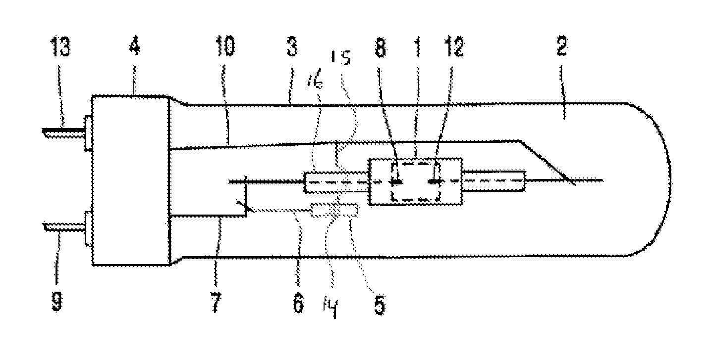
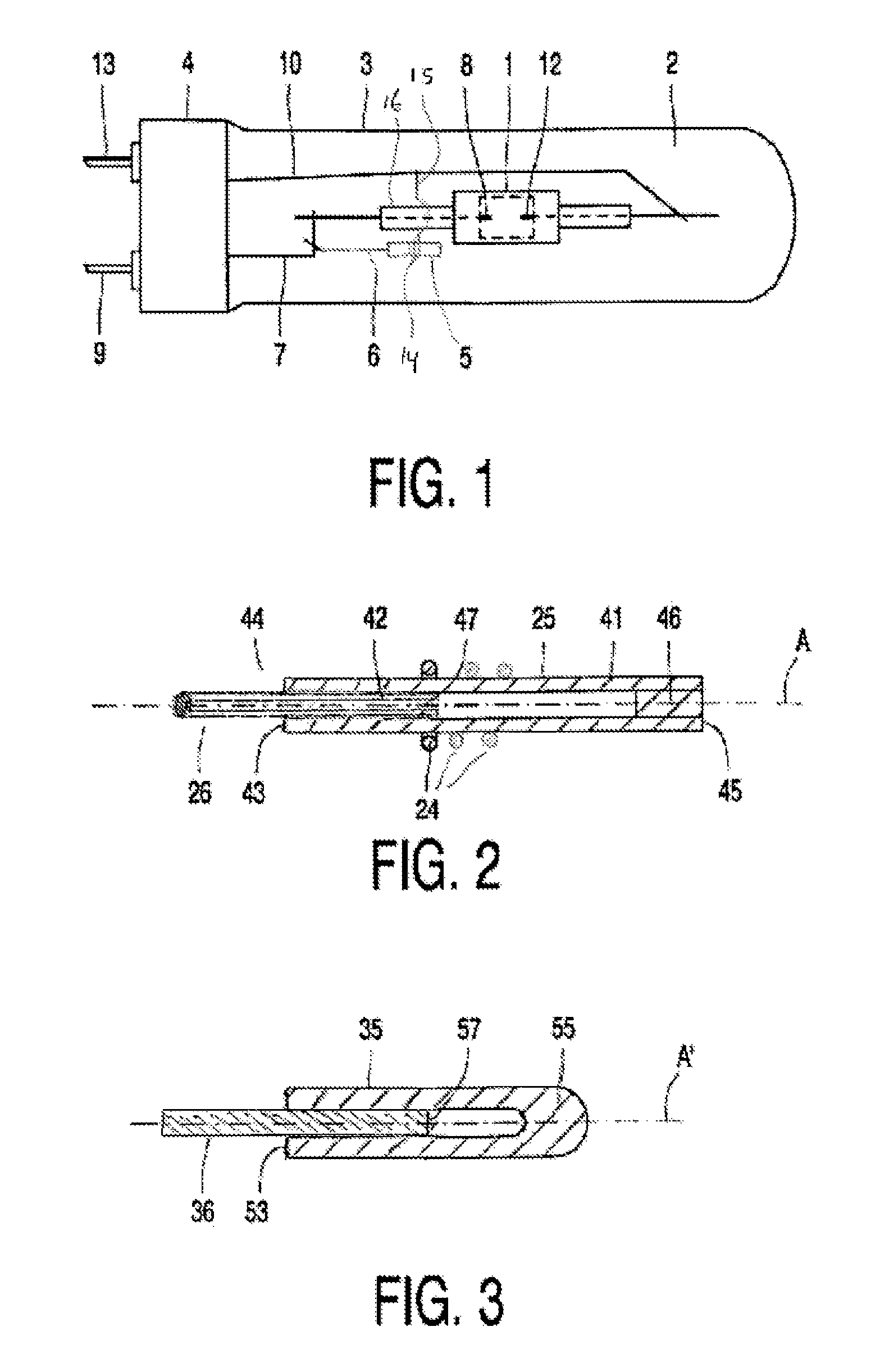
[0030]FIG. 1 shows a high-pressure metal halide lamp comprising a discharge vessel 1 surrounded with an interspace 2 by an outer envelope 3, which supports a lamp cap 4. The discharge vessel 1 is made of densely sintered polycrystalline aluminum oxide and has a first lamp electrode 8 and a second lamp electrode 12, which electrodes are connected to contacts 9 and 13 on the lamp cap 4 by means of current supply wires 7 and 10, respectively. The lamp is provided with an UV enhancer 5, which is situated in the interspace 2. Said UV-enhancer is positioned in close proximity to a connection between the current supply wire 7 and electrode 8 inside an end part (VUP) 16. The UV enhancer has an internal enhancer electrode (not shown here; see 42 in FIG. 2) which is connected to the first lamp electrode 8 by means of a lead-through wire 6. The UV enhancer has a capacitive coupling with the second lamp electrode 12. This coupling is constituted by a metal curl 14, which is connected to the sec...


PUM


Abstract

A high pressure gas discharge lamp comprising a discharge vessel, an outer envelope enclosing said discharge vessel with an interspace between the outer envelope and the discharge vessel. A UV-enhancer having a wall enclosing an electrode space with a filling gas and an internal electrode extending from the electrode space through the wall to the interspace. Said UV-enhancer is arranged in said interspace between the outer envelope and the discharge vessel, said wall of the UV-enhancer being made of ceramic material and contains said filling gas. The electrode is directly sealed into the wall.

Description

CROSS-REFERENCE TO PRIOR APPLICATIONS[0001]This application is the U.S. National Phase application under 35 U.S.C. §371 of International Application No. PCT / IB2012 / 056868, filed on Nov. 30, 2012, which claims the benefit of U.S. Provisional Patent Application No. 61 / 566,040, filed on Dec. 2, 2011. These applications are hereby incorporated by reference herein.FIELD OF THE INVENTION[0002]The invention relates to a high-pressure gas discharge lamp comprising a discharge vessel, an outer envelope enclosing said discharge vessel with an interspace between the outer envelope and the discharge vessel,[0003]an UV-enhancer having a wall enclosing an electrode space with a filling gas and an internal electrode extending from the electrode space through the wall to the interspace, said UV-enhancer being arranged in said interspace between the outer envelope and the discharge vessel, said wall of the UV-enhancer being made of ceramic material.BACKGROUND OF THE INVENTION[0004]A known problem in...

Claims


Application Information

Patent Timeline
Patent Type & Authority Patents(United States)
IPC IPC(8): H01J61/54H01J61/073H01J61/36H01J9/32
CPCH01J61/547H01J9/323H01J61/363H01J61/54H01J61/0735
Inventor VRIES, FRANCISCUS LEONARDUS GERARDUS
Owner SIGNIFY HLDG BV
Why Eureka
Try Eureka