System for mounting an electrical fixture to an electrical junction box

a technology for mounting systems and electrical fixtures, which is applied in the direction of electric cable installations, lighting and heating apparatus, lighting support devices, etc., can solve the problems of cumbersome installation for a single individual, a large number of such fixtures can represent a significant expense in the construction process, and the fixture is difficult to moun

Active Publication Date: 2015-06-23
CANARM
View PDF22 Cites 64 Cited by
  • Summary
  • Abstract
  • Description
  • Claims
  • Application Information

AI Technical Summary

Problems solved by technology

In many cases, the step of mounting a fixture to the junction box is a time-consuming process requiring forming individual connections of multiple wires, followed by fastening the fixtures to the junction boxes.
Installation of a large number of such fixtures can represent a significant expense in the construction process, in particular when the labour is largely carried out by licensed electricians.
As well, installation can be cumbersome for a single individual, particularly when installing a relatively heavy electrical fixture such as a ceiling fan or chandelier.

Method used


Image

  • System for mounting an electrical fixture to an electrical junction box
  • System for mounting an electrical fixture to an electrical junction box
  • System for mounting an electrical fixture to an electrical junction box

Examples


first embodiment

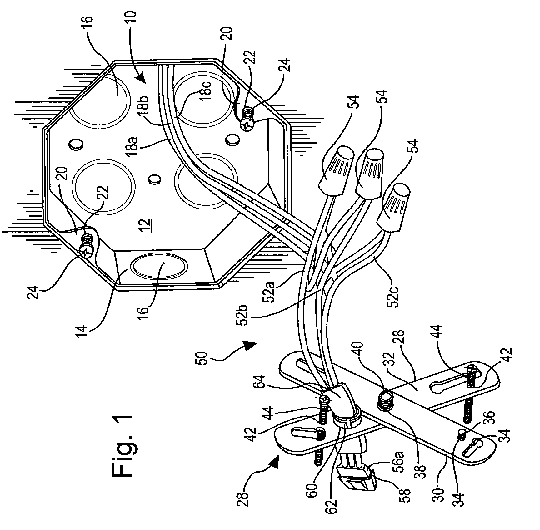
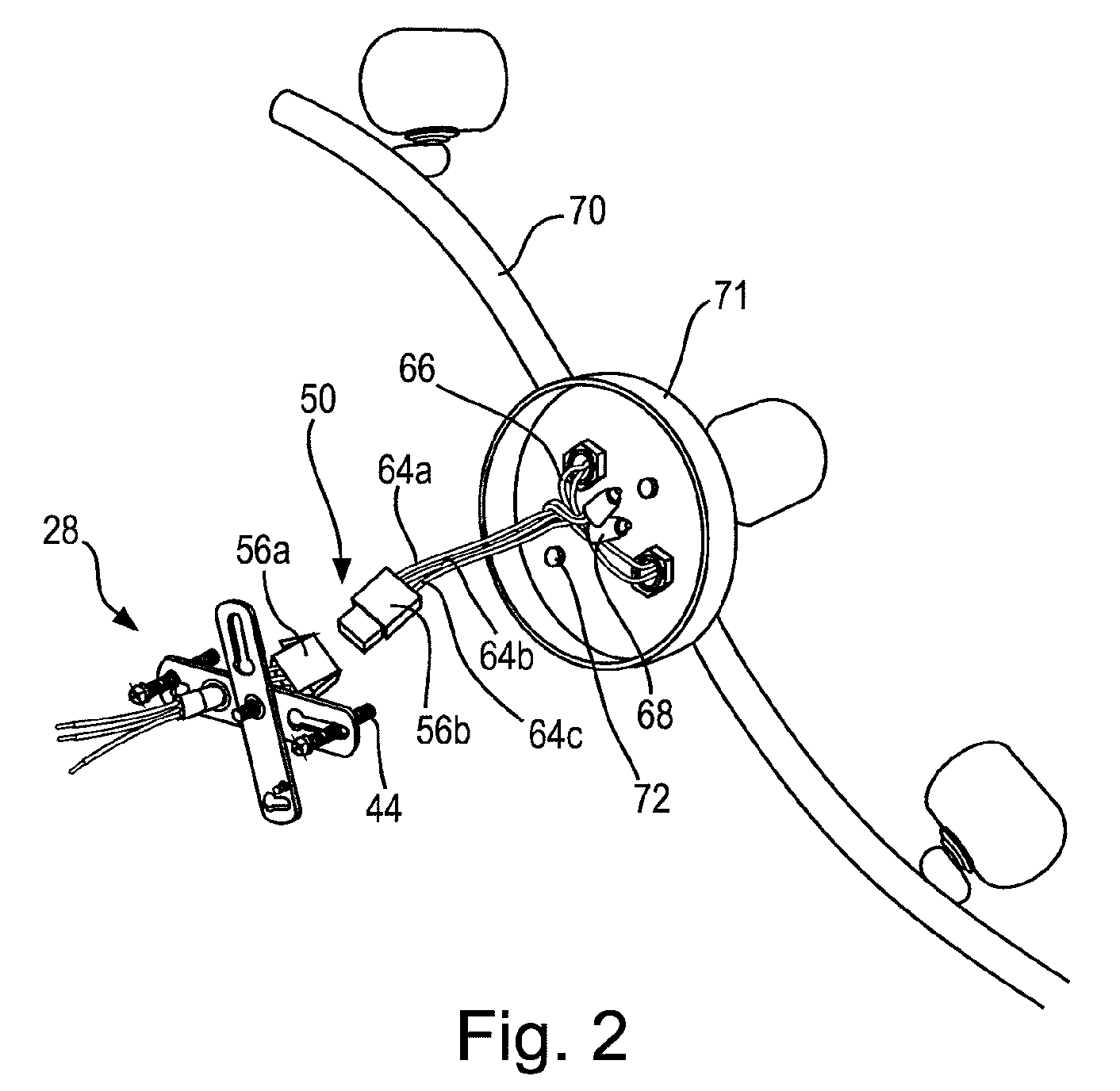
[0031]Referring to FIGS. 1-5, one embodiment of the present mounting system comprises a fixture mount 28 which when installed according to the present invention is interposed between junction box 10 and an electrical fixture 70. In the first embodiment, fixture mount 28 comprises first and second elongate flat plates 30 and 32 respectively, which are rotatably coupled at their respective midpoints to form an essentially planar X-shaped structure. However, it will be seen that in some embodiments, fixture mount 28 may alternatively comprise a single monolithic plate or other member which may be interposed between the junction box and electrical fixture.

[0032]First plate 30 includes bolt-accepting slots 34 at opposing ends for receiving bolts 24 to fasten mount 28 to junction box 10. Slots 34 are spaced to permit alignment with apertures 22 of junction box 10, so as to permit plate 34 to be bolted onto tabs 20 of junction box 10.

[0033]Second plate 32 has a similar configuration to fir...

second embodiment

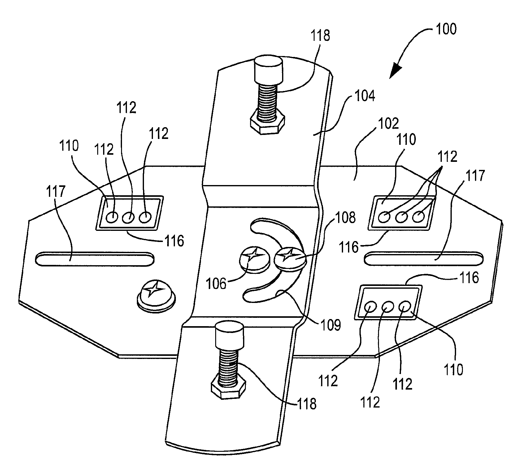
[0045]FIGS. 6 and 7 show the invention. According to this embodiment, a fixture mount member 100 comprises a two-part structure composed of base plate 102 and fixture mount plate 104. Plates 102 and 104 connect together intermediate their respective ends by way of a pivot connector 106, such as a centrally-located screw that fastens respective plates 102 and 104 together and permits rotation of the respective plates. Plates 102 and 104 are fixed in position relative to each other by a set screw 108 on plate 102. Screw 108 travels within a semicircular slot 109 within plate 104 to permit adjustment of the angular position of plates 102 and 104 relative to each other. When the respective plates are at a selected position, screw 108 may be tightened to engage plate 104 to plate 102.

[0046]Base plate 102 supports an array of three electrical connectors 110. Connectors 110 each comprise a conventional “push in” type of connector, which permits rapid connection to electrical wires by the s...


PUM

PropertyMeasurementUnit
dimensionsaaaaaaaaaa
electricalaaaaaaaaaa
currentaaaaaaaaaa

Abstract

The invention provides a mount for installing an electrical fixture to an electrical junction box. The mount includes a support configured for independent attachment to said junction box and said electrical fixture respectively for mounting said fixture to said junction box. The mount further includes at least one electrical quick connect member engaged to said support comprising a first connection element for forming an electrical connection with a electrical wire and a second connection element for forming an electrical connection a fixture electrical wires. The first and second connection elements are electrically connected or connectible together to form an electrical connection between the source wires and the fixture wires.

Description

FIELD OF THE INVENTION[0001]The present invention relates to mounting systems for electrical fixtures such as lighting fixtures, fans and the like. More specifically, the invention relates to a system and method for mounting an electrical fixture to an electrical junction box for rapid and efficient mounting of the fixture to a wall, ceiling or other surface.BACKGROUND OF THE INVENTION[0002]Electrical fixtures such as lighting fixtures, fans and the like are typically installed by mounting the fixture directly to an electrical junction box. Electrical junction boxes are typically installed within a wall, ceiling, or other surface. A typical junction box includes a rigid open-fronted compartment with mounting tabs projecting across the open front. Normally, the junction box is installed in a recessed fashion within the surface to provide a flush mount of the fixture against the surface. The mounting tabs include threaded openings for accepting screws or bolts for mounting a fixture, ...

Claims


Application Information

Patent Timeline
Patent Type & Authority Patents(United States)
IPC IPC(8): H02G3/16H02G1/00H02G3/18H02G3/14
CPCH02G3/16H02G1/00H02G3/14H02G3/18Y10T29/49208F21V21/03H02G3/20
Inventor COOPER, JAMES A.KUAN, HON MAN
Owner CANARM
Why Eureka
Try Eureka