Supercharge Your Innovation With Domain-Expert AI Agents!

Power supply enclosure and method of manufacturing the same

a technology of power supply enclosure and enclosure, which is applied in the direction of closed casing, electrical apparatus, cabinet/cabinet/drawer, etc., can solve the problems of lower production volume, difficulty in recovering the development cost of die, and the non-proportionality of the power supply in mass production compared with the enclosure cost in die developmen

Active Publication Date: 2015-06-23
CHICONY POWER TECH CO LTD
View PDF5 Cites 0 Cited by
  • Summary
  • Abstract
  • Description
  • Claims
  • Application Information

AI Technical Summary

Benefits of technology

This approach provides flexibility and reduces costs by allowing modifications to side panels without reproducing the bottom base, enabling efficient production of enclosures with different specifications using shared dies, thus minimizing unnecessary die development and production costs.

Problems solved by technology

However, the cost of the power supply in mass production compared with the cost of the enclosure in die developments is non-proportional.
The lower production volume is difficulty to recover the development cost of die.

Method used


Image

  • Power supply enclosure and method of manufacturing the same
  • Power supply enclosure and method of manufacturing the same
  • Power supply enclosure and method of manufacturing the same

Examples


Embodiment Construction

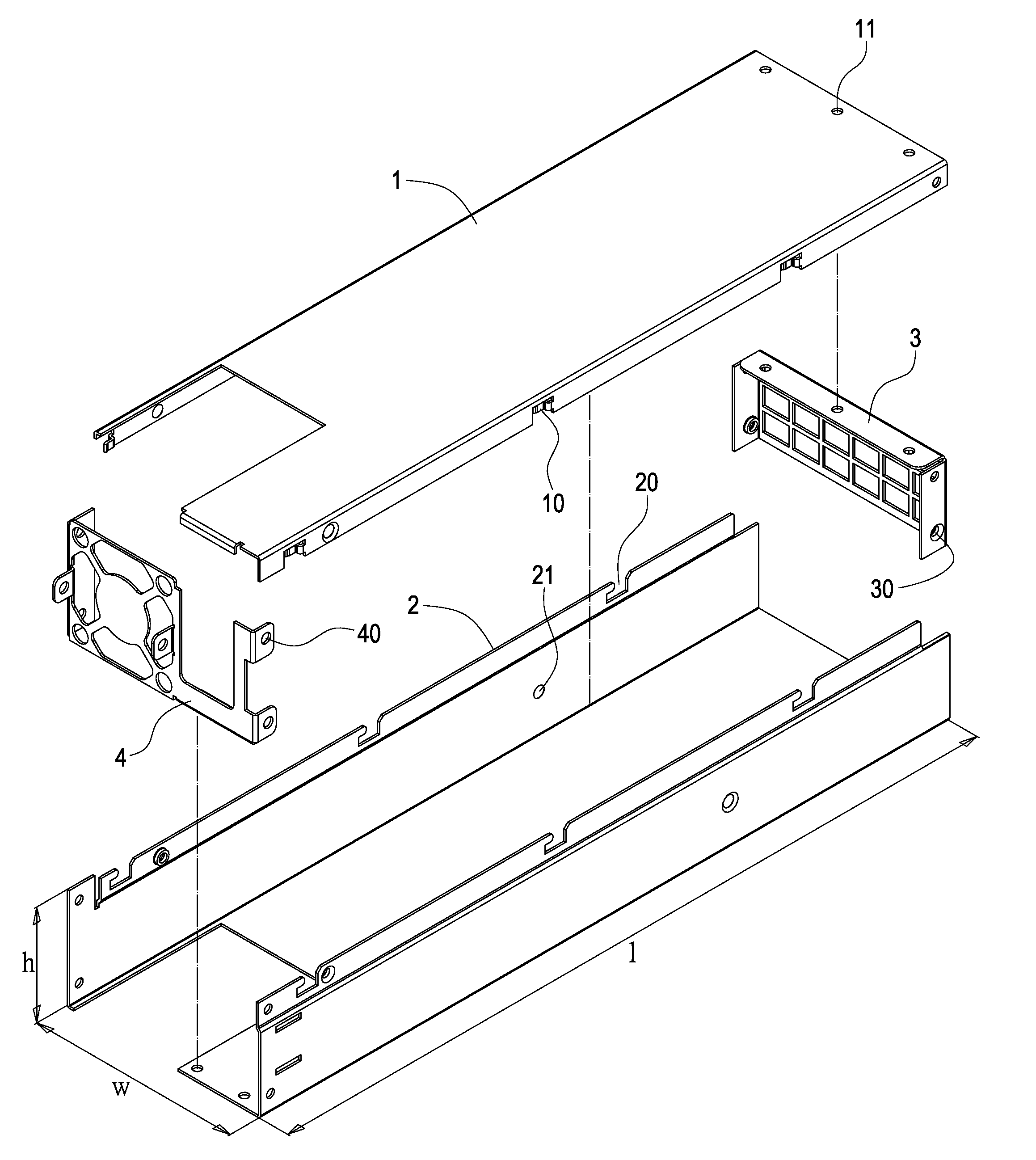
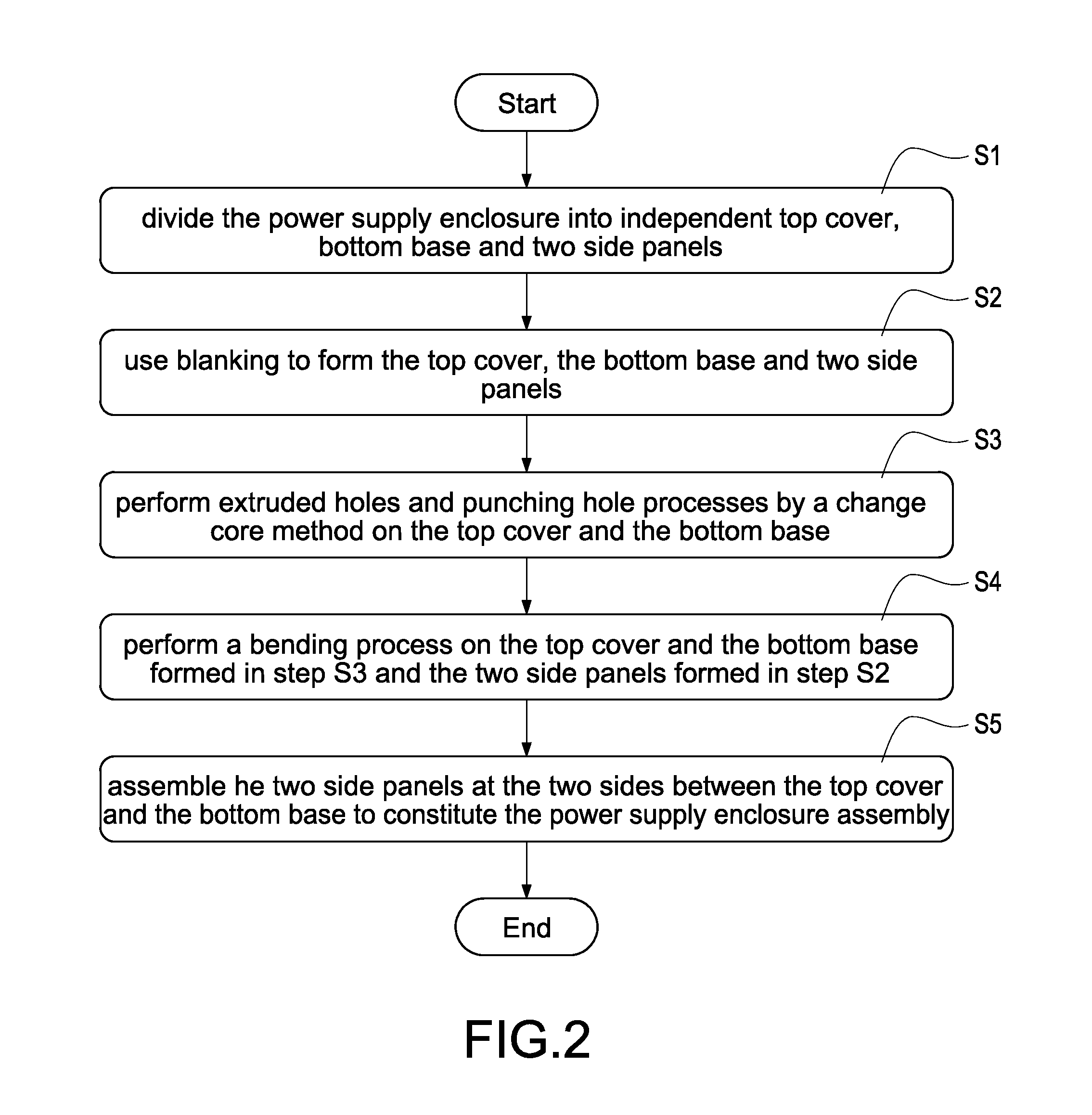
[0020]Please refer to FIG. 2 and FIG. 3. FIG. 2 is process flow of the present application and FIG. 3 shows the exploded view of the power supply enclosure assembly according to one embodiment of the present application. A power supply enclosure and a manufacturing method of the same are provided. The power supply enclosure can be divided into an independent top cover 1, an independent bottom base 2 and two independent side panels 3 and 4 as shown in FIG. 2. FIG. 3 shows that the present application has more flexibility in the use of die by means of change core method to achieve the purpose on meeting a variety of different enclosure specifications. As shown, the design allows the bottom base 2 and two side panels 3 and 4 to be disassemble into three independent components. The power supply enclosure can be constructed by four detachable components, including the bottom base 2, the two side panels, and the top cover 1.

[0021]The following processes can be carried out on each of the f...


PUM

PropertyMeasurementUnit
shapesaaaaaaaaaa
dimensionsaaaaaaaaaa
dimensionaaaaaaaaaa

Abstract

In a power supply enclosure and a method of manufacturing the same, the power supply enclosure is divided into an independent top cover, an independent bottom base, as well as two independent side panels. The top cover, the bottom base, and the side panels are formed by blanking. After extruded hole, punching or bending processes by using a change core method, the top cover and the bottom base were made, followed by assembling the two side panels on the two sides between the top cover and the bottom base to form the power supply enclosure group.

Description

BACKGROUND[0001]1. Technical Field[0002]The present application relates to a power supply, and more particularly, to a power supply enclosure and a method of manufacturing the same.[0003]2. Related Art[0004]As shown in FIG. 1, the enclosure of a conventional power supply includes an enclosure 1a made by sheet metal stamping, bending, and assembling. The enclosure 1a includes a top cover 10a and a bottom base 11a. The top cover 10a and the bottom base 11a are formed by different die stamping, followed by bending process, respectively. The bottom base 11a includes a side panel 110a integrally formed thereon by a punching process and a bending process. The top cover 10a is disposed on the bottom base 11a to complete the power supply enclosure 1a. [0005]However, the power supply with different specifications often results in enclosures 1a in different shapes and dimensions. Even if the top cover 10a and the bottom base 11a have the same dimension, the design of the side panels 110a may ...

Claims


Application Information

Patent Timeline
Patent Type & Authority Patents(United States)
IPC IPC(8): H05K5/04H05K5/00B23P15/00
CPCH05K5/0013Y10T29/49956Y10T29/49826Y10T29/49963
Inventor LEE, CHIH-HANGHSIAO, YUNG-HUNGCHANG, PEI-LICHEN, YEN-MINGHO, CHI-CHANG
Owner CHICONY POWER TECH CO LTD
Features
  • R&D
  • Intellectual Property
  • Life Sciences
  • Materials
  • Tech Scout
  • Unparalleled Data Quality
  • Higher Quality Content
  • 60% Fewer Hallucinations
Learn More