Image forming apparatus

a technology of forming apparatus and cleaning member, which is applied in the direction of electrographic process apparatus, instruments, optics, etc., can solve the problems of increasing the amount of toner sticking to the surface of the adsorption member, and the inability to remove toner from the surface, so as to increase the winding quantity of the cleaning member

Active Publication Date: 2015-07-07
SHARP KK
View PDF3 Cites 1 Cited by
  • Summary
  • Abstract
  • Description
  • Claims
  • Application Information

AI Technical Summary

Benefits of technology

[0012]The electric potential difference forming means causes the toner scattered from the paper sheet to stick to the surface of the adsorption member by forming an electric potential difference between the toner and the surface of the adsorption member. This ensures that the toner scattered from the paper sheet is adsorbed by the adsorption member. As a result, it is made possible for the image forming apparatus to remove the toner from the surface of the adsorption member by the cleaning means, and thereby to surely collect the scattered toner.
[0014]The fuser unit is disposed downstream form the paper sheet guide. With such a configuration employed in the fuser unit that includes the fixing rotational member that is heated and the pressing rotational member that is in contact with the fixing rotational member with pressure, either the fixing rotational member or the pressing rotational member can also serve as the adsorption member. This makes it possible to realize a main component of a toner collector using the fuser unit that is essential to an image forming process. Thereby apparatus cost increase and apparatus upsizing can be suppressed as compared with a case where an adsorption member is provided separately.
[0018]In this configuration, when the operating section accepts the setting for printing without margin, because the toner image is transferred onto the paper sheet as far as at least the one edge portion thereof in the width direction perpendicular to the conveyance direction, the toner is more likely to be scattered from the paper sheet than when the setting for printing without margin is not accepted. The scattered toner sometimes sticks to the pressing rotational member of the fuser unit. In the case where the operating section accepts the setting for printing without margin, the control section causes the winding quantity of the cleaning member per unit time that is in contact with the surface of the pressing rotational member and thereby cleans the surface of the pressing rotational member to be increased as compared with the case where the operating section does not accept the setting for printing without margin. This enables, in the case where the setting for printing without margin is made, the cleaning member to be wound before the cleaning member becomes unable to remove the toner from the surface of the pressing rotational member. Then, in the case where the setting for printing without margin is not made, the control section causes the cleaning member that is not dirty not to be wound because the cleaning member can remove the toner from the surface of the pressing rotational member.
[0020]In this configuration, when the operating section accepts the setting for printing without margin, because the toner image is transferred onto the paper sheet as far as at least the one edge portion thereof in the width direction perpendicular to the conveyance direction, the toner is more likely to be scattered from the paper sheet than when the setting for printing without margin is not accepted. The scattered toner sometimes sticks to the fixing rotational member of the fuser unit. In the case where the operating section accepts the setting for printing without margin, the control section causes the winding quantity of the cleaning member per unit time that is in contact with the surface of the fixing rotational member and thereby cleans the surface of the fixing rotational member to be increased as compared with the case where the operating section does not accept the setting for printing without margin. This enables, in the case where the setting for printing without margin is made, the cleaning member to be wound before the cleaning member becomes unable to remove the toner from the surface of the fixing rotational member. Then, in the case where the setting for printing without margin is not made, the control section causes the cleaning member that is not dirty not to be wound because the cleaning member can remove the toner from the surface of the fixing rotational member.
[0021]Moreover, in the case where the operating section accepts the setting for printing without margin, the control section controls the drive section in such a manner as to increase the winding quantity of the cleaning member per unit time as a size of the paper sheet becomes larger.
[0022]In the case where the setting for printing without margin is made, since the amount of the toner transferred to the outside of the paper sheet becomes more as the size of the paper sheet becomes larger, the amount of the toner scattered within the interior of the image forming apparatus becomes more; accordingly, the amount of the toner sticking to the adsorption member (fixing rotational member, pressing rotational member) increases. The control section, by controlling the drive section in such a manner as to increase the winding quantity of the cleaning member per unit time, can more surely remove the toner from the surface of the adsorption member.

Problems solved by technology

Further, when the operating section accepts the setting for printing without margin, since more toner is scattered from the paper sheet than when the operating section does not accept the setting for printing without margin, the amount of the toner sticking to the surface of the adsorption member increases.
In the case where the setting for printing without margin is made, the control section causes the cleaning member to be wound before the cleaning member becomes dirty due to the toner sticking thereto and thus unable to remove the toner from the surface of the adsorption member.

Method used


Image

  • Image forming apparatus
  • Image forming apparatus
  • Image forming apparatus

Examples


first embodiment

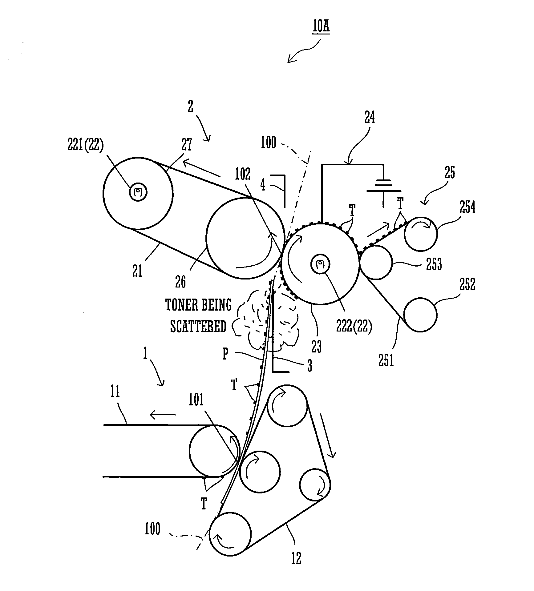
[0030]Embodiments of the present invention are explained below, referring to the drawings. An essential part of an image forming apparatus 10A according to the present invention is shown in FIG. 1. Since other configurations that constitute the image forming apparatus 10A but are not shown in the above drawing are of those widely known, their illustrations and explanations are omitted. The image forming apparatus 10A of the present invention is an image forming apparatus adapted for printing without margin that forms an image by transferring a toner image onto an imaging area and a margin of a paper sheet. In the printing without margin, an image is formed by forming a toner image beyond a width of a paper sheet P and transferring the toner image onto the paper sheet P as far as an edge portion thereof.

[0031]As shown in FIG. 1, the image forming apparatus 10A includes a transfer station 101 and a fuser section 102 that are formed along a paper sheet conveying path 100 where the pape...

third embodiment

[0064]An image forming apparatus 10B cleans the surface of the endless belt 21 by the cleaning mechanism 25.

[0065]As shown in FIG. 6, the abutting roller 253 causes the web 251 that is sent out from the send-out roller 252 to be brought into contact with the surface of the endless belt 21. The web 251 is configured in such a manner that a surface thereof in contact with the surface of the endless belt 21 is moved gradually from the send-out roller 252 toward the take-up roller 254. The endless belt 21 is an example of the adsorption member of the present invention.

[0066]Also, as shown in FIG. 5, when the operating section 6 accepts the order to start the image forming process, because the toner is scattered in the case where the setting for printing without margin is made, the control section 5 sets the winding quantity of the web 251 per unit time to a value three times larger as compared with the case where the setting for printing without margin is not made. This makes it possib...

fourth embodiment

[0067]An image forming apparatus 100 includes a cleaning mechanism 28 that cleans the surface of the endless belt 21.

[0068]As shown in FIG. 7, the cleaning mechanism 28 has the same structure as the cleaning mechanism 25, and cleans the surface of the endless belt 21. This ensures that the scattered toner T that sticks to the endless belt 21 without being electrostatically adsorbed by the pressing roller 23 can also be collected surely. The web 251 and the web 281 are examples of a first cleaning member and a second cleaning member of the present invention, respectively.

[0069]Moreover, in the image forming process, in the case where the setting for printing without margin is not made in the process of S12, as shown in FIG. 5, the control section 5, referring to the contents stored in the memory section 7, set a winding quantity x of the webs 251, 281 to X (=0.7 mm) (S13). Also, in the case where the setting for printing without margin is made in the process of S12, the control sect...


PUM


Abstract

An image forming apparatus includes a pre-fusing paper sheet guide, a fuser unit and a control section. The pre-fusing paper sheet guide is disposed adjacent to the fuser unit on its upstream side. The fuser unit includes a pressing roller having, an electrically conductive surface, a grounding structure grounding a pressing roller's surface, and a cleaning mechanism cleaning the pressing roller's surface. The cleaning mechanism includes a web and a take-up roller. The control section sets a winding quantity x of the web to 0.7 mm when a setting for printing without margin is not made, and sets the winding quantity x to 2.1 mm when the setting for printing without margin is made. If the number of sheets accumulated through the image forming process becomes not less than 18, the control section causes the take-up roller to wind the web by the winding quantity x, and performs an image forming process.

Description

CROSS REFERENCE[0001]This Nonprovisional application claims priority under 35 U.S.C. §119(a) on Patent Application No. 2013-124650 filed in Japan on Jun. 13, 2013, and Patent. Application NO. 2014-056379 filed in Japan on Mar. 19, 2014, the entire contents of which are hereby incorporated by reference.BACKGROUND OF THE INVENTION[0002]The present invention relates to an image forming apparatus having a function of printing without margin that forms an image by transferring a toner image onto an imaging area and a margin of a paper sheet.[0003]Among image forming apparatus are there ones having a function of printing without margin that forms an image onto an imaging area and a margin of a paper sheet, as well as ones forming an image onto an imaging area of a paper sheet leaving a margin blank.[0004]An image forming apparatus according to the electrophotography method forms an image onto a paper sheet through an imaging process in which a toner image is formed on a surface of an imag...

Claims


Application Information

Patent Timeline
Patent Type & Authority Patents(United States)
IPC IPC(8): G03G15/20G03G21/00
CPCG03G21/00G03G15/2021G03G15/2025
Inventor NAKAMURA, HIROKAZUSHINKAWA, TATSUYANAMISAKI, KOUSUKEOHTA, MOTOKI
Owner SHARP KK
Why Eureka
Try Eureka