Circular lock assembly

a lock assembly and circuit technology, applied in the field of circuit lock assembly, can solve the problems of retailers losing more than $33 billion annually, and achieve the effects of reducing locking and unlocking time, preventing theft and misplacement, and being easy to mount and unmoun

Active Publication Date: 2015-07-14
MCHATET HAMID
View PDF17 Cites 9 Cited by
  • Summary
  • Abstract
  • Description
  • Claims
  • Application Information

AI Technical Summary

Benefits of technology

[0025]It is therefore one of the main objects of the present invention to provide a circular lock assembly that secures products displayed on a look hoop system to prevent theft and misplacement.
[0026]It is another object of this invention to provide a circular lock assembly that can be readily mounted and unmounted without the need of any tools.
[0027]It is another object of this invention to provide a circular lock assembly that minimizes locking and unlocking time.
[0028]It is another object of this invention to provide a circular lock assembly that is volumetrically efficient for carrying, transporting, and storage.
[0029]It is another object of this invention to provide a circular lock assembly, which is of a durable and reliable construction.
[0030]It is yet another object of this invention to provide such a device that is inexpensive to manufacture and maintain while retaining its effectiveness.

Problems solved by technology

Retailers lose more than $33 billion annually due to inventory shrinkage that typically results from theft and misplacement.

Method used


Image

  • Circular lock assembly
  • Circular lock assembly
  • Circular lock assembly

Examples


Embodiment Construction

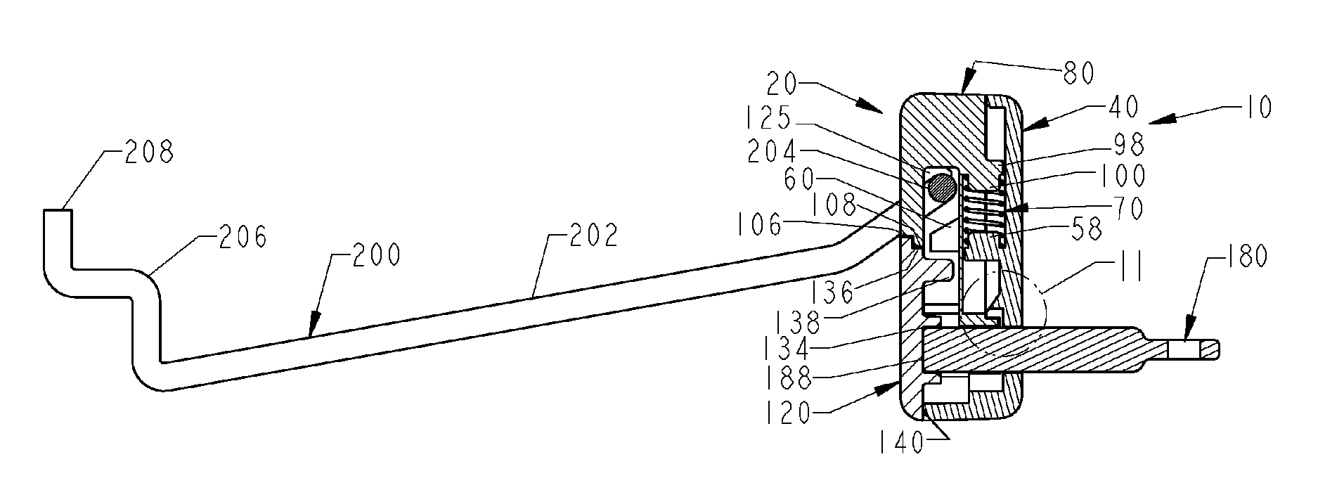
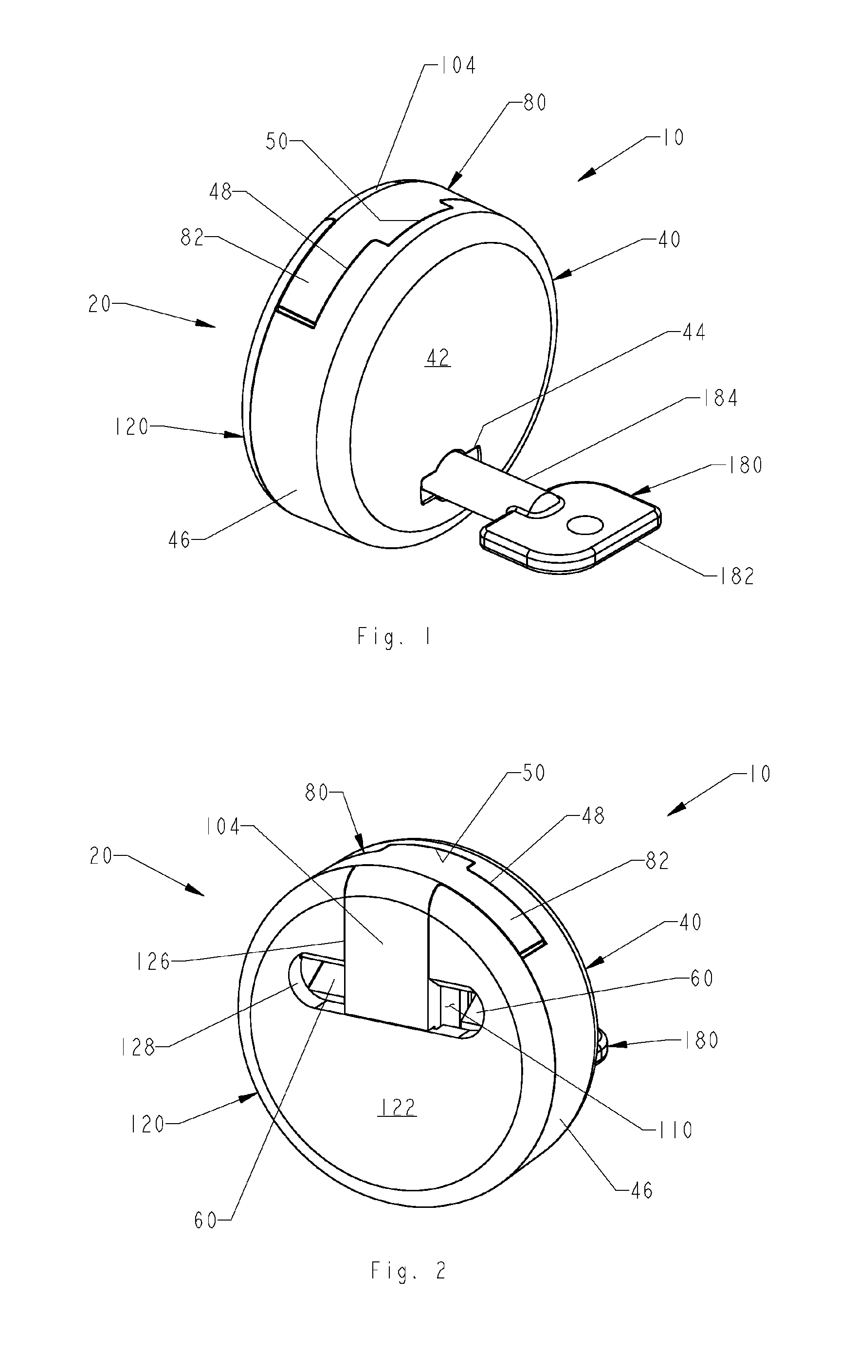
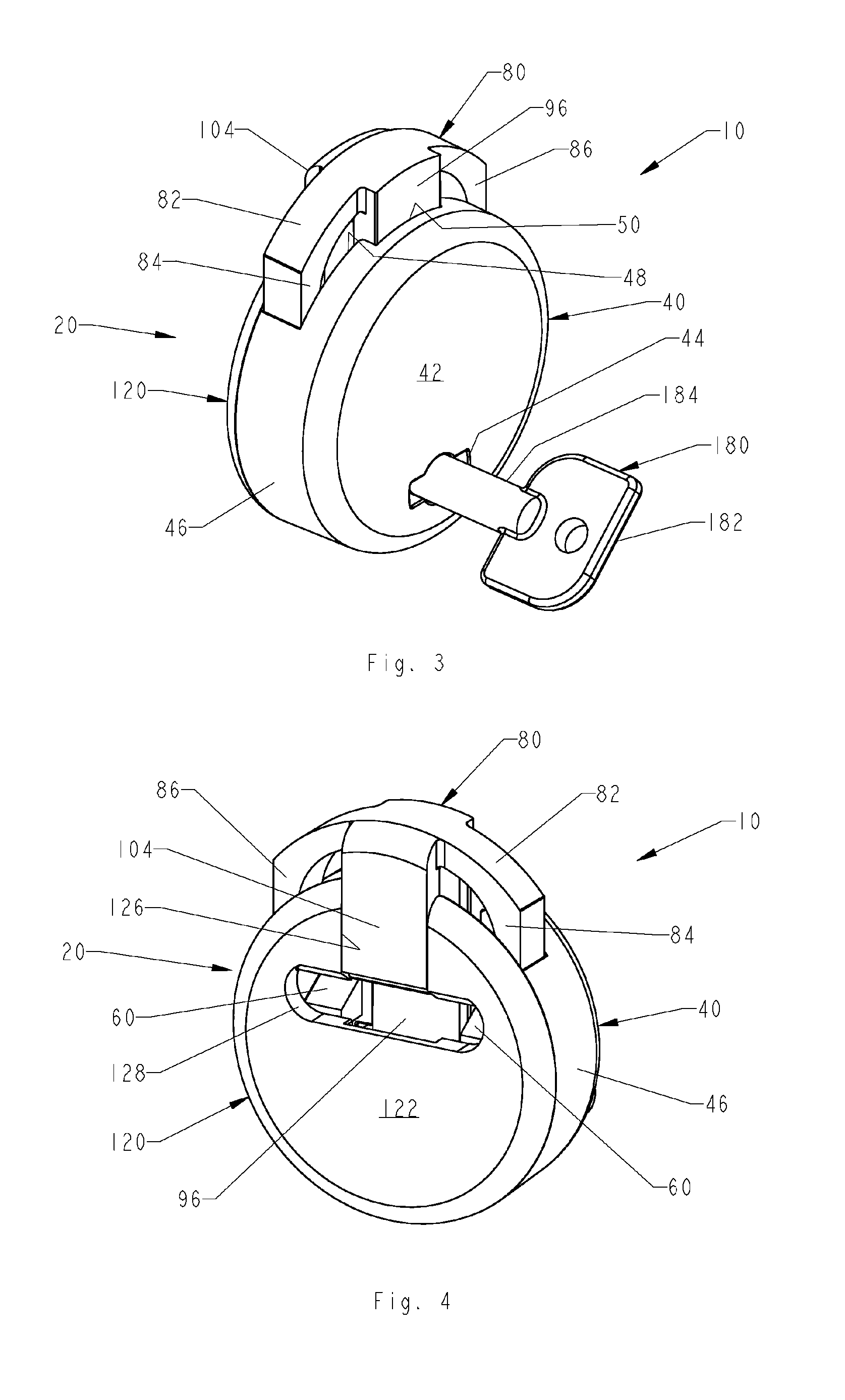
[0048]Referring now to the drawings, the present invention is a circular lock assembly and is generally referred to with numeral 10. It can be observed that it basically includes lock assembly 20 and key 180. Circular lock assembly 10 is used with rail assemblies 200, usually mounted to display racks in stores, not shown, to prevent removal of packaging suspended therefrom.

[0049]As seen in FIGS. 1, 2, 3, and 4, lock assembly 20 comprises front housing 40, slider assembly 80, and cover plate assembly 120.

[0050]Front housing 40 has front wall 42 with keyhole 44. Keyhole 44 has a cooperative dimension and shape to removably receive key 180 therethrough. Front housing 40 also has sidewall 46 with cutout 48 and notch 50. Slider assembly 80 is sandwiched in between front housing 40 and cover plate assembly 120. As best seen in FIGS. 3 and 4, slider assembly 80 basically comprises slider frame 82, arms 84 and 86, slider column 96, and locking tab 104. As best seen in FIGS. 2 and 4, cover p...


PUM


Abstract

A lock assembly having a front housing with a locking member. The front housing houses a spring. A slider assembly has a locking ramp. The locking ramp is engaged by the locking member when the slider assembly is in a locked configuration. A cover plate assembly has a transversal opening. The transversal opening receives a transversal member of a rail assembly when the slider assembly is in an unlocked configuration. The slider assembly has a locking tab that blocks the transversal opening when the slider assembly is in the locked configuration. Thus, securing the transversal member to prevent removal of packaging suspended from the rail assembly. A key inserted into a keyhole, is rotated to cause the locking ramp to disengage from the locking member to place the slider assembly is in the unlocked configuration.

Description

BACKGROUND OF THE INVENTION[0001]1. Field of the Invention[0002]The present invention relates to lock assemblies, and more particularly, to a circular lock assembly that secures products displayed on a look hoop system to prevent theft and misplacement.[0003]2. Description of the Related Art[0004]Retailers lose more than $33 billion annually due to inventory shrinkage that typically results from theft and misplacement. Reducing inventory shrinkage is an important store management issue that must be addressed to achieve and maintain a successful operation. In an effort to increase owner profits, retailers have a need for an easy, simple, and inexpensive lock assembly to secure products displayed on a look hoop system to help prevent theft and product misplacement.[0005]Applicant believes that one of the closest references corresponds to Applicant's own U.S. Pat. No. 7,269,983 issued on Sep. 18, 2007 for a lock assembly. However, it differs from the present invention because Applicant...

Claims


Application Information

Patent Timeline
Patent Type & Authority Patents(United States)
IPC IPC(8): E05B73/00A47F5/08
CPCE05B73/00A47F5/0861E05B35/08E05B67/36E05C19/06
Inventor MCHATET, HAMID
Owner MCHATET HAMID
Why Eureka
Try Eureka