Portable solar-powered devices

a solar-powered device and solar energy technology, applied in the direction of lighting support devices, light source combinations, with built-in power, etc., can solve the problems of short-lived current lighting options, inconvenient operation, inconvenient maintenance, etc., and achieve the effect of improving the service life, reducing the cost of production and operation, and improving the service li

Active Publication Date: 2015-07-14
MPOWERD
View PDF32 Cites 44 Cited by
  • Summary
  • Abstract
  • Description
  • Claims
  • Application Information

AI Technical Summary

Benefits of technology

The present patent describes a collapsible solar-powered lighting device that includes a housing, a solar panel, LEDs, a rechargeable battery, and a microprocessor. The housing has a first wall, a second wall, and one or more side walls that define an inflatable bladder. The solar panel is integrated into the first or second wall. The LEDs are integrated into the electronics wall of the housing. The rechargeable battery is connected between the solar panel and the LEDs. The microprocessor controls the LEDs and can change the color of light emitted from the device. The device can be controlled by a user through a button integrated into the housing. The technical effects of the invention include a flexible solar-powered lighting device that is easy to assemble, has a long-lasting battery, and can change the color of light emitted from the device.

Problems solved by technology

The technical problem addressed by this patent is the need for reliable and efficient alternatives to traditional lighting methods when there is no available electrical power or limited power availability. Current lighting options can be unreliable, costly, and difficult to use with existing infrastructure.

Method used


Image

  • Portable solar-powered devices
  • Portable solar-powered devices
  • Portable solar-powered devices

Examples


Embodiment Construction

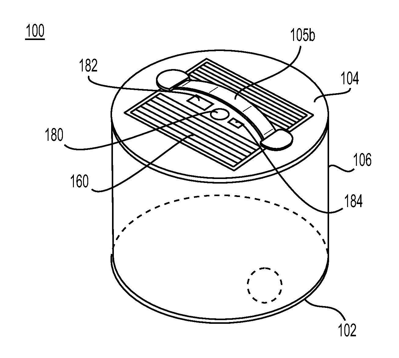
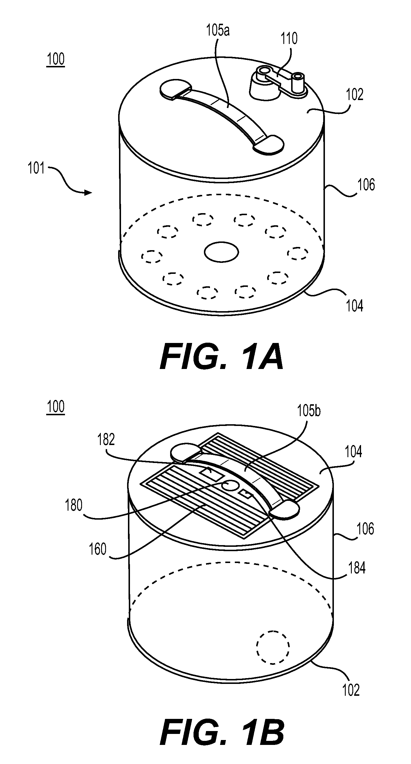
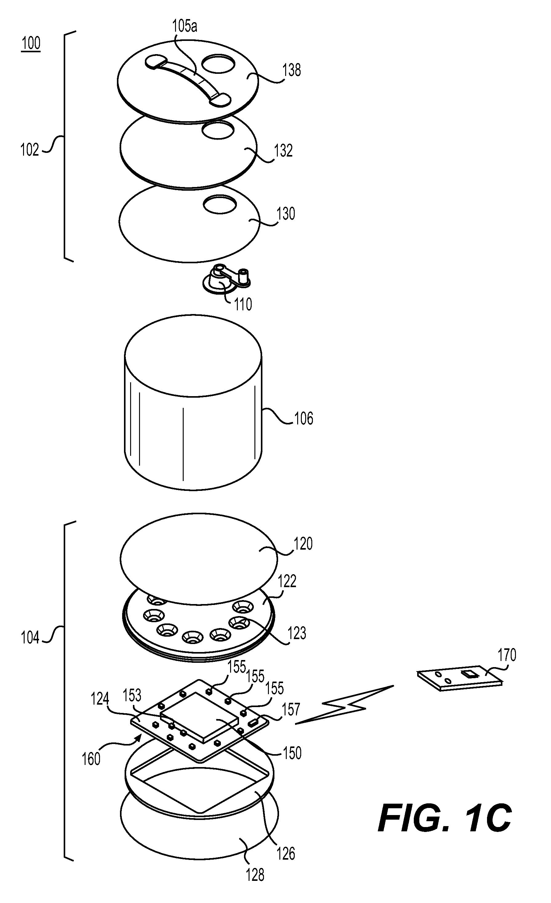
[0020]Embodiments of the present disclosure include solar-powered lighting devices that may be portable and / or collapsible.

[0021]FIGS. 1A-1C illustrate an exemplary lighting device 100 comprising an inflatable housing 101, such that the device 100 may have a collapsed configuration (e.g., for storage, recharging, or otherwise when not in use) and an expanded, inflated configuration (e.g., for use). The housing 101 may include a first wall 102, a second wall 104, and one or more side walls 106 between the first wall 102 and the second wall 104, wherein the side wall(s) 106 may be collapsible, e.g., to allow the device 100 to deflate and inflate. For example, the first wall 102, second wall 104, and one or more side walls 106 may define an inflatable bladder. The first wall 102 and the second wall 104 may be positioned opposite each other, e.g., generally parallel, or any other suitable configuration. The devices of the present disclosure are not limited to any particular orientation ...


PUM


Abstract

Solar-powered lighting devices that may be portable and/or collapsible are described. The devices may include a housing including a first wall, a second wall, and one or more side walls between the first wall and the second wall, at least one solar panel to generate solar energy, and a rechargeable battery to store the solar energy generated. The devices may include a plurality of operating modes for controlling lights within the housing, and a microprocessor for controlling the operating modes.

Description


Claims


Application Information

Patent Timeline
Owner MPOWERD
Why Eureka
Try Eureka