Quick acting panel fastener

a fastener and retainer technology, applied in the direction of fastening means, ways, constructions, etc., can solve the problems of no known quick-acting panel fastener having a retainer, no known quarter-turn panel fastener technology, and high manufacturing cost, and achieve the effect of ultra-low cos

Active Publication Date: 2015-07-21
PEM MANAGEMENT INC
View PDF85 Cites 10 Cited by
  • Summary
  • Abstract
  • Description
  • Claims
  • Application Information

AI Technical Summary

Benefits of technology

[0005]In order to meet the needs in the art, the present panel fastener has been devised which is comprised of two separately formed interacting parts: a panel retainer and an actuator pin. The retainer is fashioned from sheet metal using progressive stamping technology. The retainer and pin work together to create a fastener that can semi-permanently snap into a first panel and then be clamped onto and then selectively removed from a second panel. The retainer snaps into a shaped hole in the first panel and the attachment to the second panel can be achieved or released by turning a knob that rotates the pin into detented self-locking positions. The head can be configured for hand actuation, tool-only actuation, or both. The present fastener is ultra-low-cost, utilizing a progressively stamped retainer and a cold-forged knob and pin.
[0006]More specifically, the Applicant has devised a panel fastener comprising a unitary stamped sheet metal retainer having a central rotating actuator pin. The retainer includes outwardly deflectable resilient barbs for providing a loose snap-in retention to a first panel through a square hole having deflector tabs for engaging the barbs upon insertion. Resilient legs on the retainer are laterally expandable for engagement with the backside of a square hole through a second panel for securing the first panel to it face-to-face. The pin is rotatably secured to the body portion of the retainer and it is manually rotatable between engaged and disengaged selected positions. The pin includes a cam on its end which co-acts with followers on the legs for selectively moving the legs to an expanded state where the pin is in the engaged position. In its expanded state, the legs of the retainer apply a resilient clamp load against the backside of the second panel. To enhance its operation, opposing sides of the expandable retainer include forked cam followers which capture opposing lobes of the cam when the pin is in the engaged position thereby holding the pin in a locked position.

Problems solved by technology

However, this technology is not known to have been successfully applied to quarter-turn panel fasteners.
While these attempts in the art to provide a quick-acting or quarter-turn panel fastener, they are very expensive parts to manufacture.
There is no known quick-acting panel fastener having a retainer made from a unitary sheet metal stamping.

Method used


Image

  • Quick acting panel fastener
  • Quick acting panel fastener
  • Quick acting panel fastener

Examples


Embodiment Construction

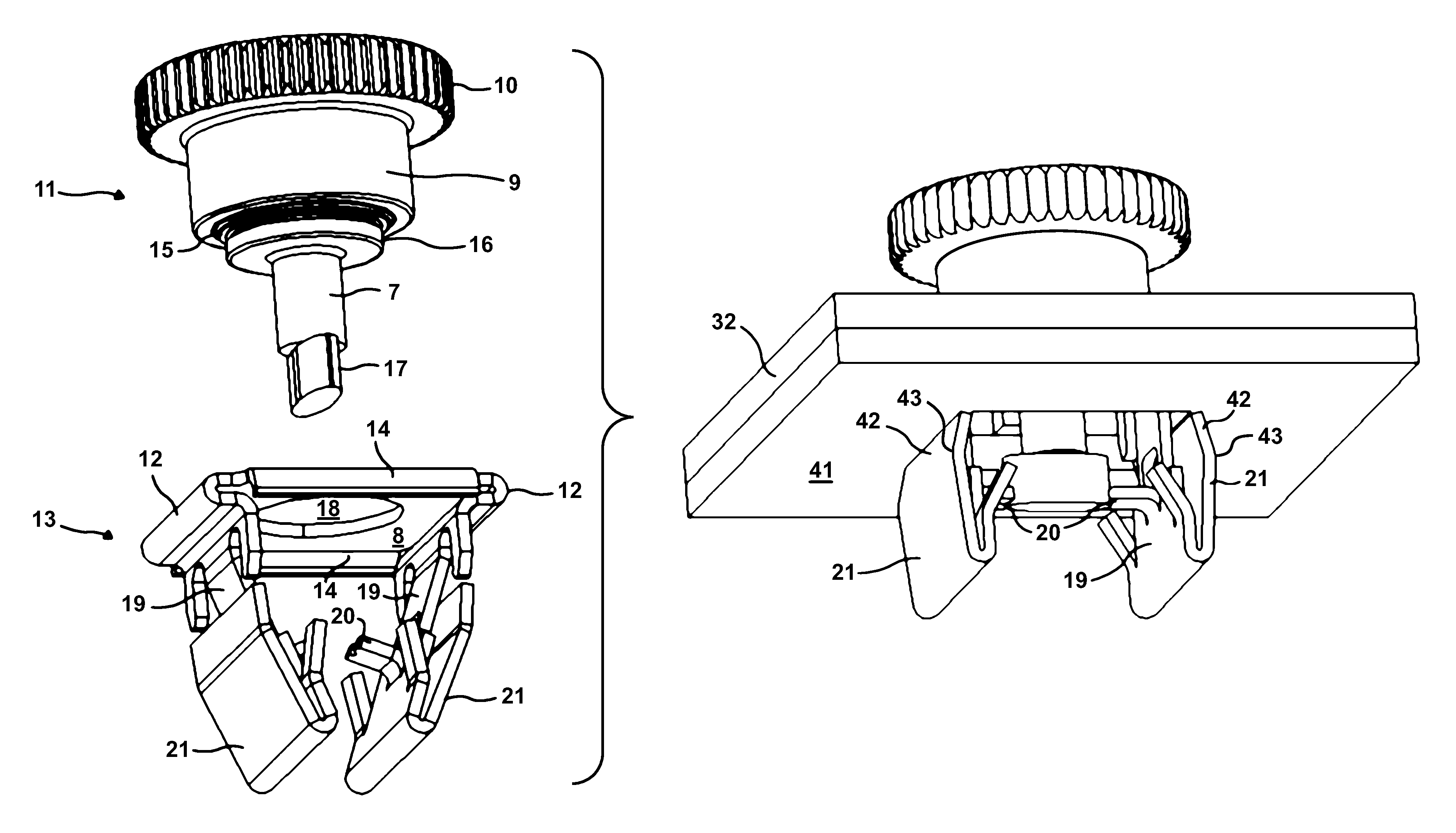
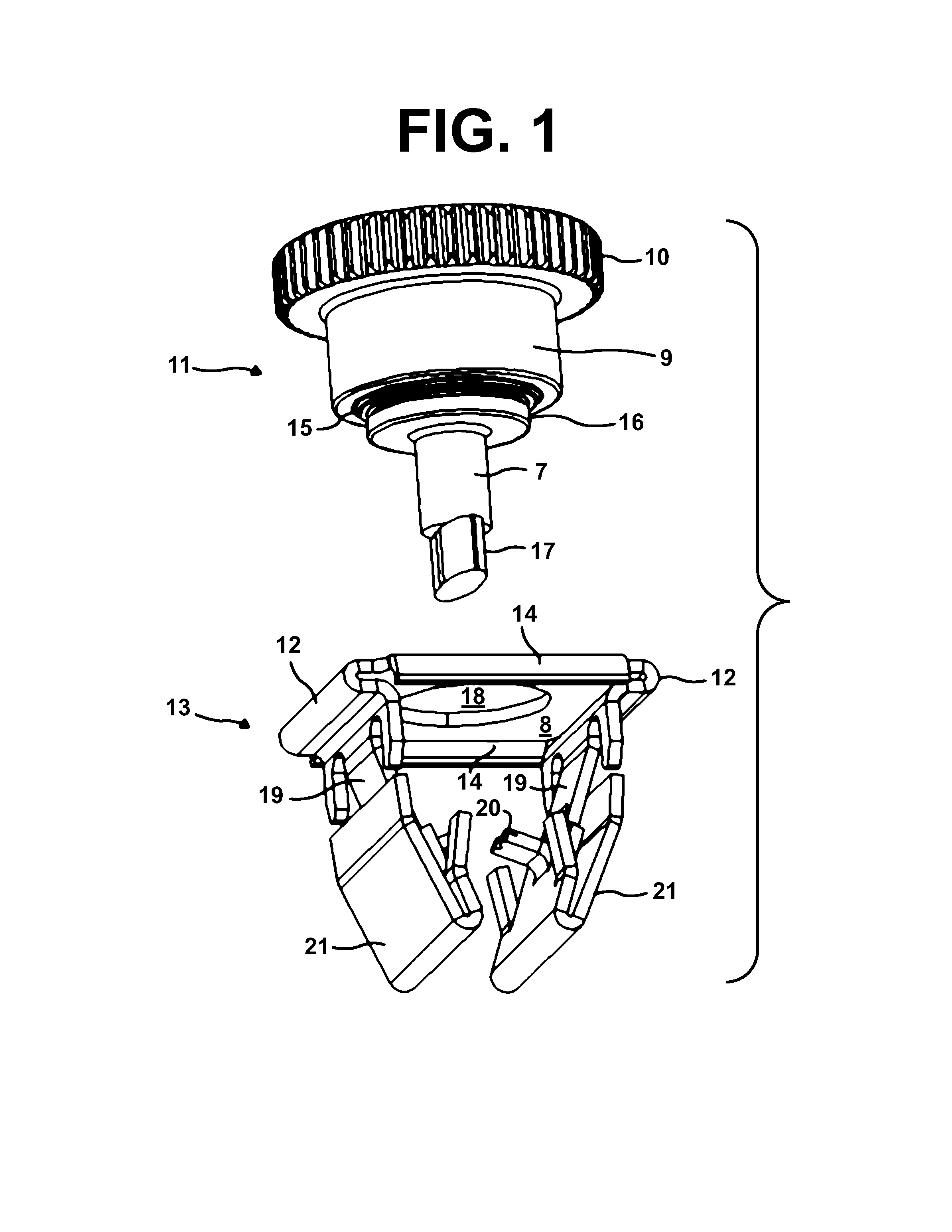
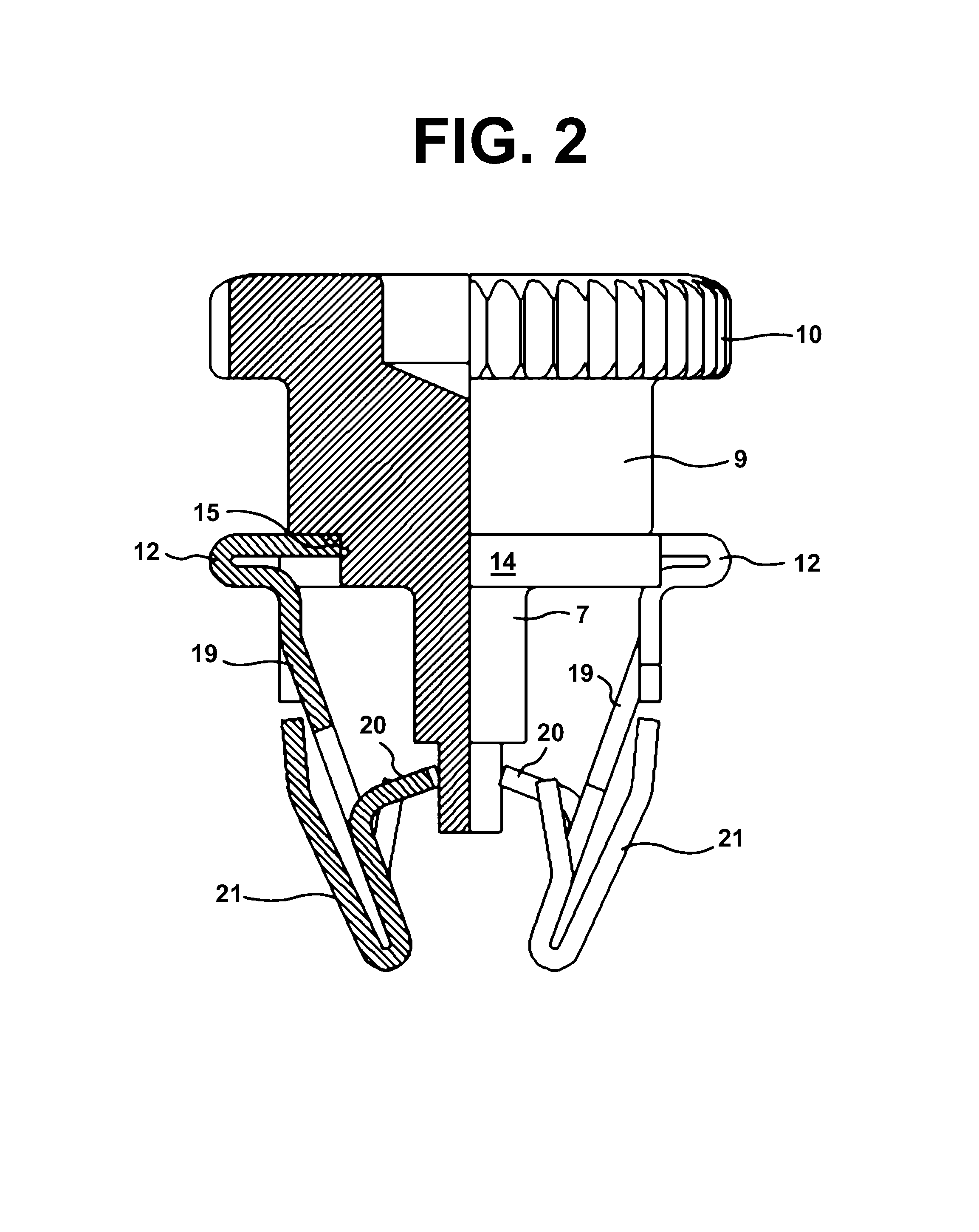
[0014]Referring now to FIGS. 1 and 2, the present fastener is comprised of two components, an actuator pin 11 and a retainer 13. The end of the pin 11 carries an elliptical cam 17 with two lobes 180° apart providing a narrow cross-section and a wide cross-section that are 90° apart. A shank portion 7 of the pin extends between the cam and the head 9 of the pin. Between the pin's head and shank is a flange 16 having clinch features 15 along its circumference comprising a displacer and an undercut dimensioned relative to a receiving hole in the body of the retainer to permit rotation while maintaining axial captivation. The head 9 may contain any number of features used to turn the pin such as a knurled knob 10 for manual operation as shown in this embodiment and / or a drive for tool use. Other options include a t-handle pin, phillips-drive or a slot. The pin is made using cold forging technology.

[0015]Referring now to the retainer 13 of FIGS. 1 and 2, a body portion 8 of the retainer ...


PUM


Abstract

A panel fastener is comprised of two separately formed interacting parts: a panel retainer and an actuator pin. The retainer is fashioned from sheet metal using progressive stamping technology. The retainer and pin work together to create a fastener for securing two panels together that can semi-permanently snap into the first panel and then be clamped onto and then selectively removed from the second panel. Attachment to the second panel is obtained by expanding and later released by contracting the legs of the retainer by rotating a cammed expander pin between self-locking positions. A head of the expander pin can be configured for hand actuation, tool-only actuation, or both. The retainer is fashioned from sheet metal using progressive stamping technology.

Description

RELATED APPLICATION[0001]This patent application is related to provisional patent application Ser. No. 61 / 228,314 entitled “Quick Acting Panel Fastener” filed on Jul. 24, 2009, priority from which is hereby claimed.FIELD OF THE INVENTION[0002]The present invention relates to a releasable panel fastener with a body member and a manually rotatable spindle therein. In use, the body member extends from an attached first planar panel into releasable engagement through an aperture in a second panel for the purpose of releasably interconnecting the two panels.BACKGROUND OF THE INVENTION[0003]There have been examples in the art of quick-acting panel fasteners for releasably joining two panels in face-to-face relation by inserting the fastener through aligned holes in the panels and turning one of the elements of the fastener. These fasteners are sometimes referred to as “quarter-turn” panel fasteners. A top panel is first more or less permanently affixed to a retainer part of the fastener. ...

Claims


Application Information

Patent Timeline
Patent Type & Authority Patents(United States)
IPC IPC(8): F16B21/02F16B21/20
CPCF16B21/02F16B21/20
Inventor BENTRIM, BRIANMALONEY, MICHAEL
Owner PEM MANAGEMENT INC
Why Eureka
Try Eureka