Automated implantable penile prosthesis pump system

a pump system and penile technology, applied in the field of automatic implantable penile prosthesis pump system, can solve the problems that the suction poppet may not properly engage the suction annulus, and achieve the effects of preventing vacuum lock-up of the pump bulb, limiting the travel distance and preventing uncontrolled engagement of the suction popp

Active Publication Date: 2015-07-28
BOSTON SCI SCIMED INC
View PDF101 Cites 5 Cited by
  • Summary
  • Abstract
  • Description
  • Claims
  • Application Information

AI Technical Summary

Benefits of technology

[0010]In one aspect, the flow path further defines an annular ring positioned between the suction annulus and the pump bulb opening. If the pump bulb is actuated too quickly and / or air is present within the pump bulb opening such as, for example, during the initial installation, the suction poppet can become wedged against the annular ring blocking all flow and creating a vacuum condition essentially locking the pump bulb in the compressed state. In one aspect, the suction poppet can further comprise a head extending through the suction annulus. The head can define a lip engagable by a plurality of fingers extending from the suction annulus. The fingers engage the lip when the suction poppet is slid into the disengaged position to prevent the suction poppet from engaging the annular ring and creating vacuum lock up. The fingers allow for a controlled travel distance of the suction poppet preventing vacuum lock up of the pump bulb.
[0013]A method of preventing vacuum lock up of the pump bulb, according to an aspect of the present invention, can comprise providing a suction poppet positioned between the suction annulus leading to the reservoir and the pump bulb, wherein the suction poppet further comprises an elongated head extending through the suction annulus. The method can further comprise defining a plurality of fingers extending from the suction annulus to limit the travel distance of the suction poppet and prevent uncontrolled engagement of the suction poppet to other features within the valve assembly.

Problems solved by technology

If the suction poppet becomes misaligned, the suction poppet may not properly engage the suction annulus allowing working fluid to leak through the suction annulus.

Method used


Image

  • Automated implantable penile prosthesis pump system
  • Automated implantable penile prosthesis pump system
  • Automated implantable penile prosthesis pump system

Examples


Embodiment Construction

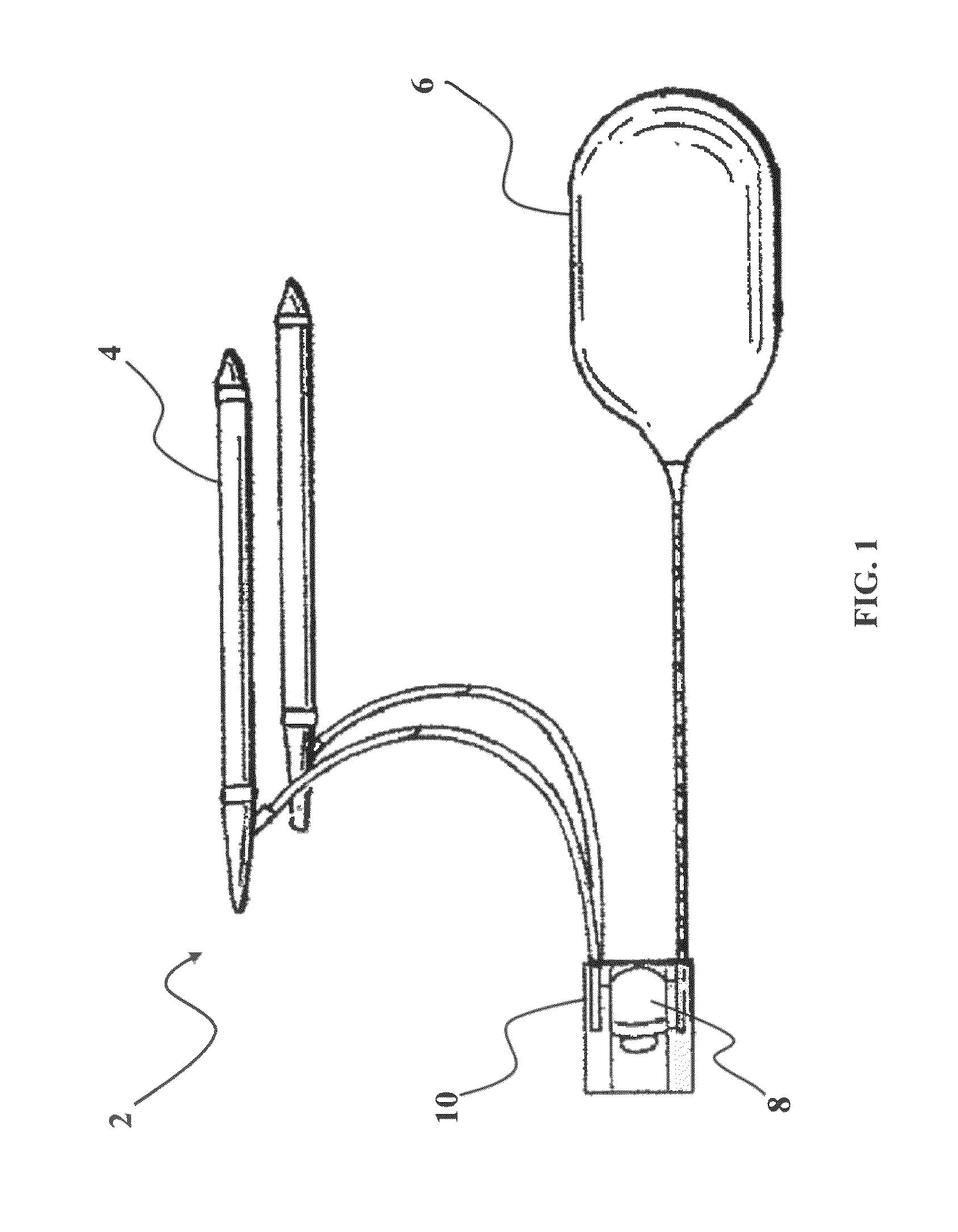
[0021]As shown in FIG. 1, an implantable penile prosthesis (IPP) 2, according to an embodiment of the present invention, comprises at least one inflatable cylinder 4, a reservoir 6, a pump 8 and a valve assembly 10. The pump 8 can further comprise a pump bulb 12 that can be compressed and released to draw and pump working fluid. The IPP 2 generally operates by actuating the pump bulb 12 to draw a quantity of working fluid from the reservoir 6 and pumping the working fluid into the inflatable cylinder 4. The valve assembly 10 is generally adapted to prevent back flow of the working fluid during operation of the pump 8 to inflate inflatable cylinder 4.

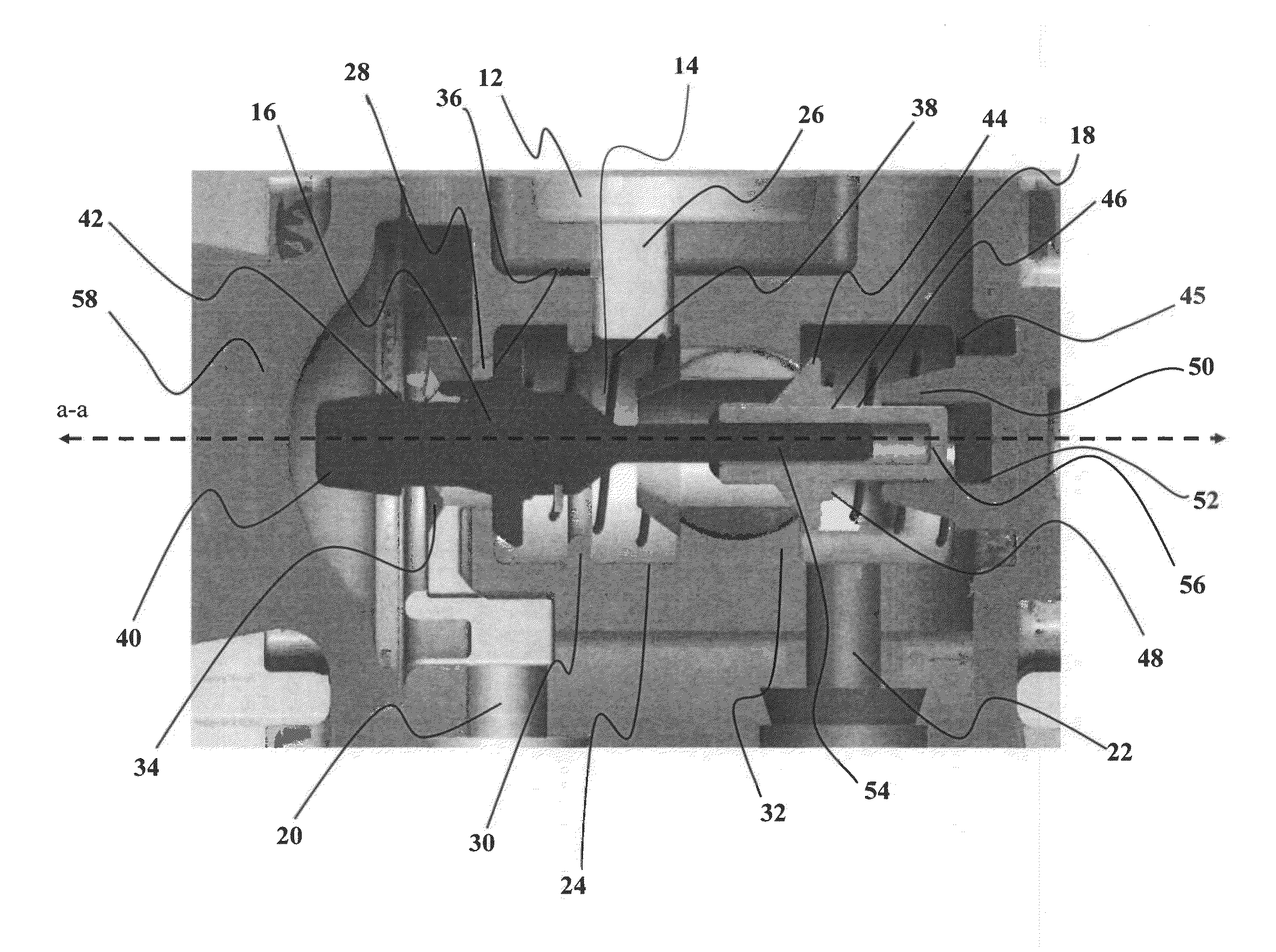
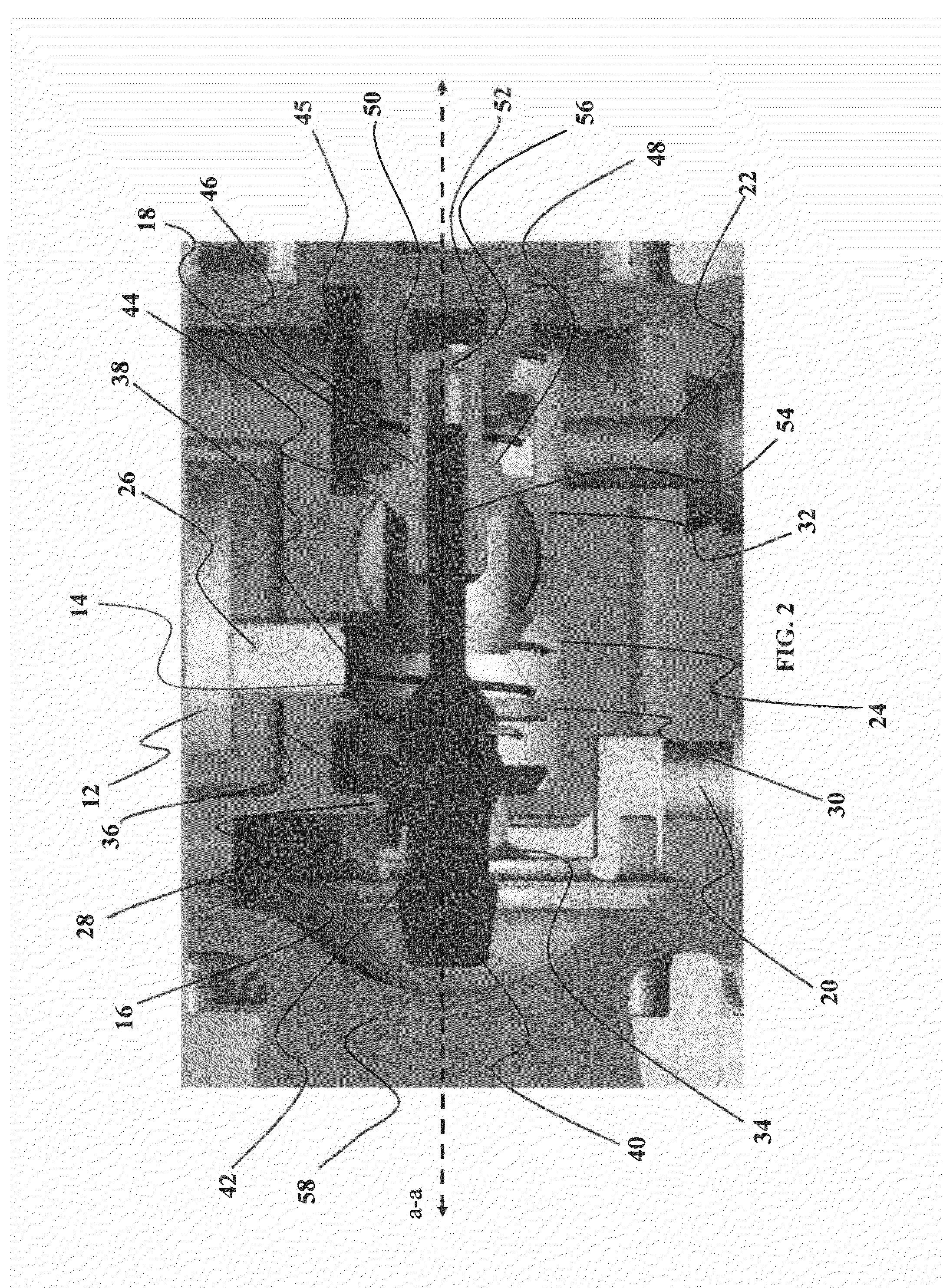
[0022]As shown in FIGS. 1-2, the valve assembly 10 defines a valve flow path 14 and comprises a suction poppet 16 and a cylinder poppet 18. The valve flow path 14 is defined between a reservoir inlet 20 from the reservoir 6 and a cylinder outlet 22 leading to the cylinder 4. The valve flow path 14 also further comprises a linear valve ch...


PUM


Abstract

A dual poppet valve assembly for a pump assembly of an implantable penile prosthesis having a suction poppet engagable by a plurality of fingers allowing free travel of the poppet and to prevent vacuum lockup of the pump assembly. The suction poppet can also include an elongated shaft receivable within a corresponding bore of a cylinder poppet to prevent the suction poppet from becoming misaligned during the operation of the pump assembly.

Description

RELATED APPLICATION[0001]The present application claims the benefit of U.S. Provisional Application No. 61 / 613,770 filed Mar. 21, 2012, and entitled “AUTOMATED IMPLANTABLE PENILE PROSTHESIS PUMP SYSTEM”, which is incorporated herein in its entirety by reference.FIELD OF THE INVENTION[0002]The present invention is generally directed to a pump system for an implantable penile prosthesis. Specifically, the present invention is directed to a suction poppet assembly for an implantable penile prosthesis pump system.BACKGROUND OF THE INVENTION[0003]Implantation of an implantable penile prosthesis (IPP) is a common surgical procedure for treating erectile dysfunction and other penile ailments. An IPP comprises an inflatable cylinder connected by a pump to a separate reservoir for holding the quantity of fill liquid via kink resistant tubing. This version of the IPP is available under the trade name AMBICOR from American Medical Systems of Minnetonka, Minn. Typically, the entire IPP is impla...

Claims


Application Information

Patent Timeline
Patent Type & Authority Patents(United States)
IPC IPC(8): A61F5/00A61F2/26
CPCA61F2/26A61M39/22A61F2/484
Inventor HENKEL, GREGORY J.ROCHELEAU, GARY A.JAHNS, SCOTT E.
Owner BOSTON SCI SCIMED INC
Why Eureka
Try Eureka