Check patentability & draft patents in minutes with Patsnap Eureka AI!

Flow path opening/closing valve

a flow path and valve body technology, applied in the direction of valve details, valve housings, valve arrangements, etc., can solve the problems of contaminating the clean fluid supplied to the flow path, affecting the operation of the valve, and mixing trace amounts of corrupted fluid, so as to facilitate the operation and prevent the contamination of the fluid that passes through the interior of the valve body

Inactive Publication Date: 2015-07-28
SMC CORP
View PDF14 Cites 2 Cited by
  • Summary
  • Abstract
  • Description
  • Claims
  • Application Information

AI Technical Summary

Benefits of technology

Prevents fluid infiltration and retention, maintaining stable sealing performance and preventing corrosion and contamination, even with prolonged use and wear, ensuring reliable fluid handling.

Problems solved by technology

When rotation of the valve is completed, the infiltrated fluid is not returned to the flow path but remains within the gap, and the retained fluid becomes altered in character and corrupted, leading to corrosion of the valve and the valve main body.
Thus, a disadvantage occurs in that trace amounts of the corrupted fluid become mixed with in the flow path and contaminate the clean fluid that is supplied to the flow path.
However, inner circumferential surfaces of the seal members 4a, 4b are continuously in sliding contact with the outer circumferential surface of the valve body 6, and therefore, when rotation of the valve body 6 is carried out continuously over a long period of time, the seal members 4a, 4b are subject to wear and the sealing function thereof deteriorates.
As a result, even in a valve-closed state, a disadvantage occurs in that fluid tends to leak from the flow path.
Furthermore, as such wearing of the seal members 4a, 4b progresses, small gaps are formed at worn locations of the seal members 4a, 4b, so that similar to the conventional technique of U.S. Pat. No. 4,815,704, part of the fluid infiltrates and becomes retained in the small gaps, whereby the valve body 6 and the first body 2a are subject to corrosion, and a disadvantage occurs in that clean fluid that passes through the flow path inside the valve body 6 becomes contaminated.

Method used


Image

  • Flow path opening/closing valve
  • Flow path opening/closing valve
  • Flow path opening/closing valve

Examples


Embodiment Construction

[0037]A preferred embodiment of a flow path opening / closing valve according to the present invention will be described below with reference to the accompanying drawings.

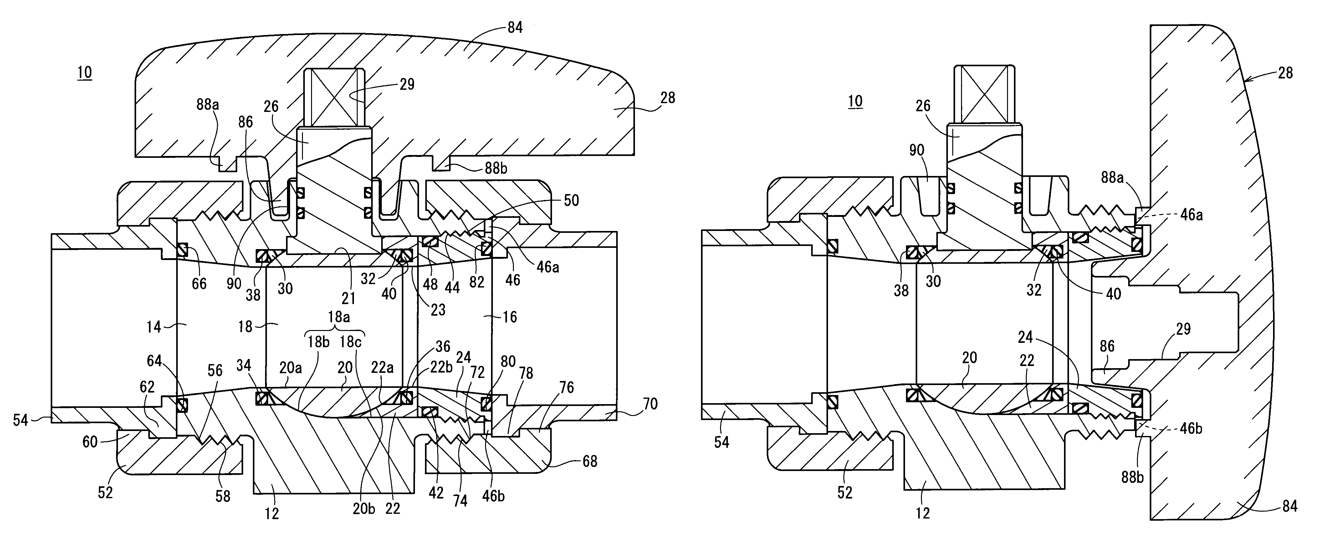
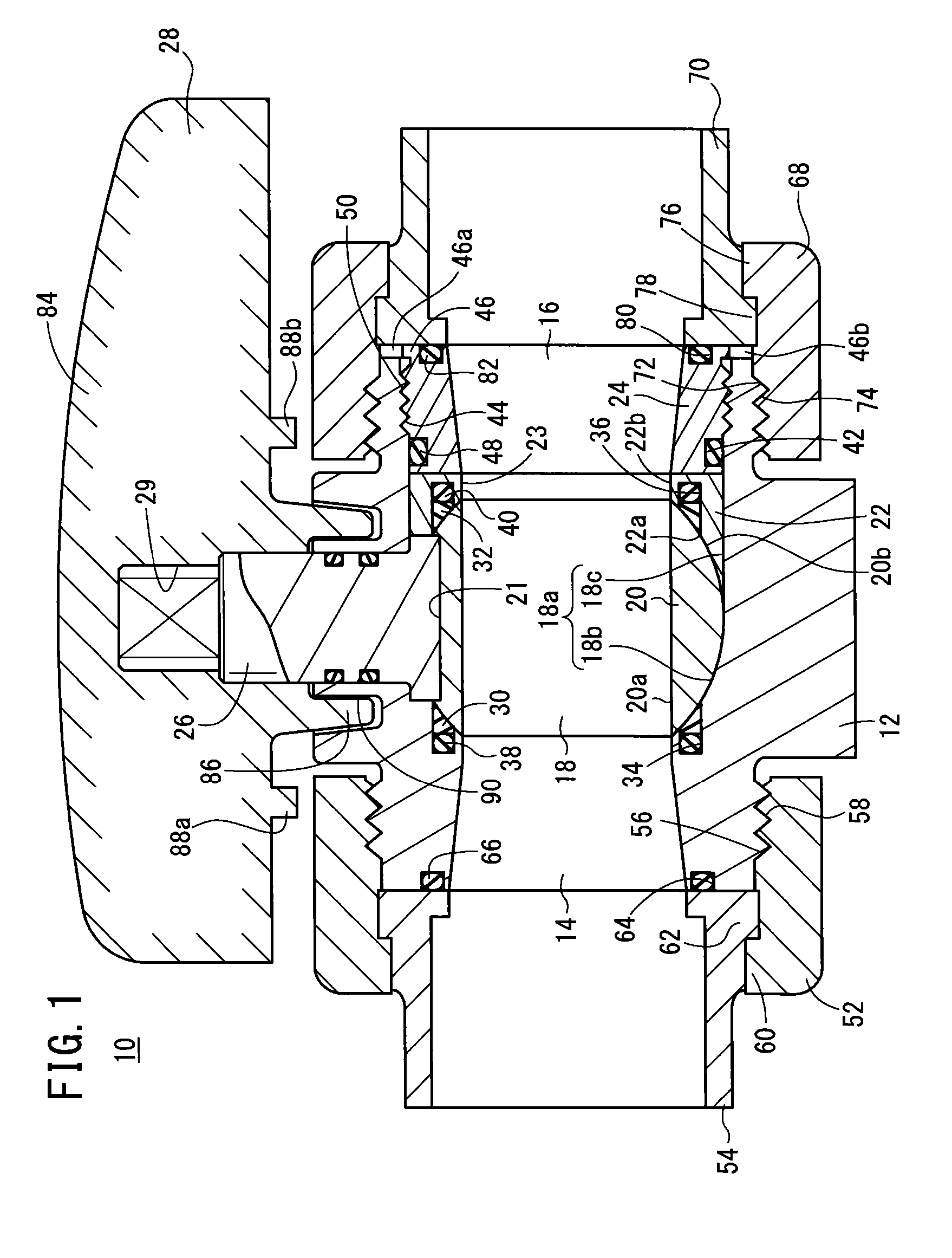
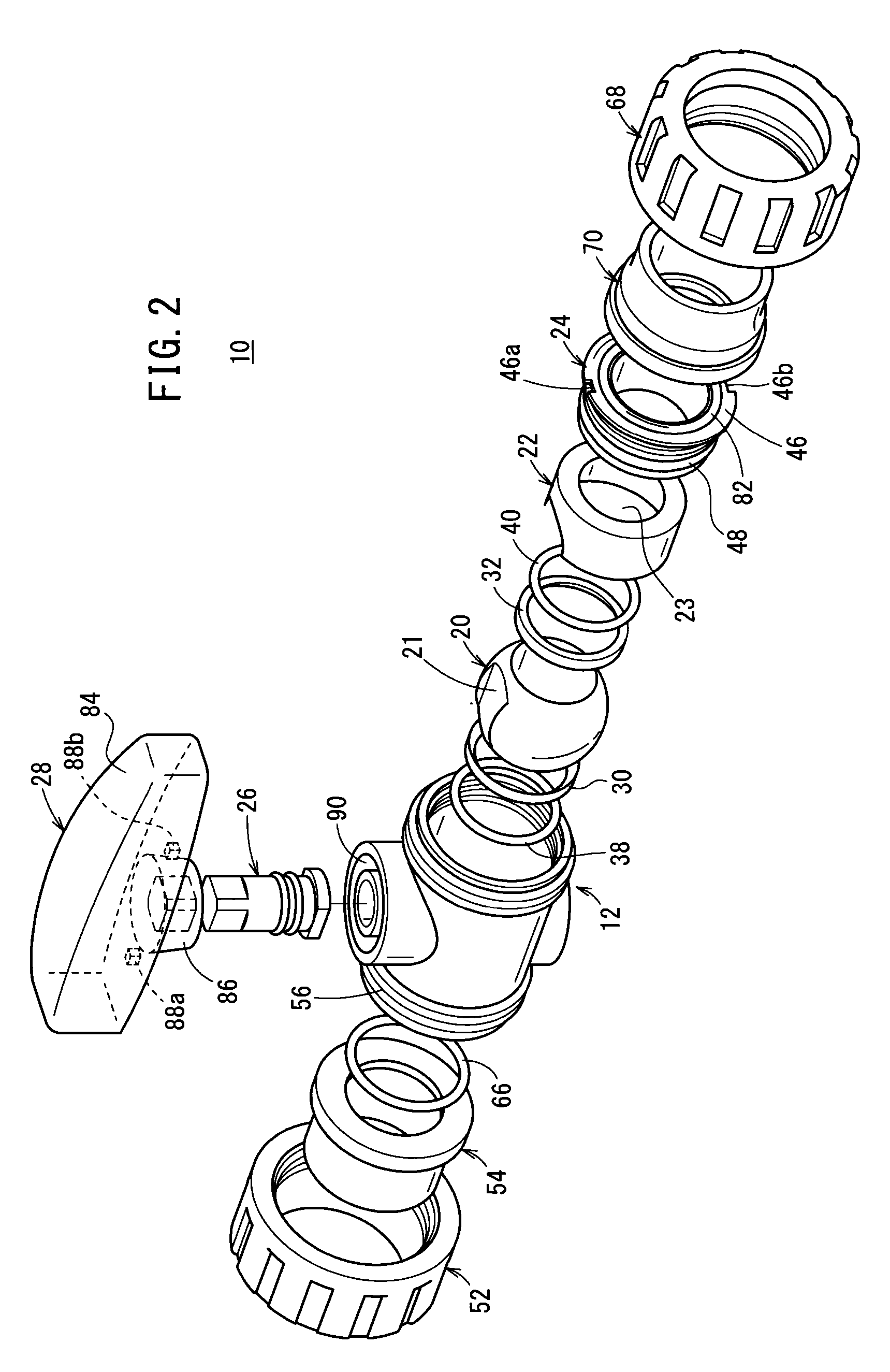
[0038]In FIG. 1, reference numeral 10 indicates a flow path opening / closing valve according to an embodiment of the present invention. The flow path opening / closing valve 10 includes a main body 12. A fluid inlet port 14 is formed on one end side of the main body 12, and a fluid outlet port 16 that communicates with the fluid inlet port 14 is formed on another end side of the main body 12.

[0039]As shown in FIGS. 1 and 2, in the main body 12, a valve chamber 18 is formed between the fluid inlet port 14 and the fluid outlet port 16. A spherical valve body 20 in which a through hole 20a is provided is accommodated rotatably in the interior of the valve chamber 18, and a sleeve 22 is arranged on the fluid outlet port 16 side of the valve body 20. The fluid inlet port 14 side of the sleeve 22 is in contact with the valve ...


PUM


Abstract

A flow path opening / closing valve is equipped with a main body having a valve chamber housing therein a rotatable valve body, and a sleeve that abuts without gaps against an inner circumferential surface of the valve chamber, such that the inner circumferential surface of the valve chamber and an inner circumferential surface of the sleeve slide without gaps against an outer circumferential surface of the valve body, for thereby shielding the valve chamber by the valve body and the sleeve. First and second seat members, and first and second o-rings that urge the first and second seat members toward the side of the valve body are arranged inside first and second annular grooves, which are provided on the inner circumferential surface and the inner circumferential surface.

Description

CROSS-REFERENCE TO RELATED APPLICATION[0001]This application is based upon and claims the benefit of priority from Japanese Patent Application No. 2012-233173 filed on Oct. 22, 2012, the contents of which are incorporated herein by reference.BACKGROUND OF THE INVENTION[0002]1. Field of the Invention[0003]The present invention relates to a flow path opening / closing valve for switching a flow through state of a fluid by opening and closing a flow path through which the fluid flows.[0004]2. Description of the Related Art[0005]Heretofore, a flow path opening / closing valve has been known which, for example, is connected to a flow path through which a fluid flows, and which controls a flow through state of the fluid by switching a state of communication of the flow path.[0006]As a flow path opening / closing valve of this type, in U.S. Pat. No. 4,815,704, there is disclosed a “ball valve” structure having a spherical valve. In the flow path opening / closing valve, a valve chamber is provided...

Claims


Application Information

Patent Timeline
Patent Type & Authority Patents(United States)
IPC IPC(8): F16K5/00F16K5/20F16K5/06
CPCF16K5/0647F16K5/0689F16K5/201F16K27/067F16K5/06F16K5/20
Inventor FUKANO, YOSHIHIROUCHINO, TADASHIHATTA, TAIYOU
Owner SMC CORP
Features
  • R&D
  • Intellectual Property
  • Life Sciences
  • Materials
  • Tech Scout
  • Unparalleled Data Quality
  • Higher Quality Content
  • 60% Fewer Hallucinations
Learn More