Non-contact power transmission apparatus

a power transmission apparatus and non-contact technology, applied in the direction of transformers/inductance details, transformers, inductances, etc., can solve the problems of short-circuiting of portable electronic devices, user touching the charging terminal and receiving an electric shock, and the magnetic flux generated at the primary coil may leak to the metal component, so as to achieve non-contact power transmission, reduce power transmission efficiency, and make thin

Inactive Publication Date: 2015-07-28
NEC CORP
View PDF15 Cites 0 Cited by
  • Summary
  • Abstract
  • Description
  • Claims
  • Application Information

AI Technical Summary

Benefits of technology

[0013]It is therefore an object of the present invention to provide a non-contact power transmission apparatus that can be made thinner without any drop in power transmission efficiency.Solution to Problem
[0015]According to the present invention, the non-contact power transmission apparatus can be made thinner without any drop in power transmission efficiency.

Problems solved by technology

Accordingly, when the charging terminal is exposed from the body of the portable electronic device, there is a possibility that the user will touch the charging terminal and receive an electric shock.
There is also a possibility that metal will touch the charging terminal to cause short-circuiting of the portable electronic device.
However, in the non-contact power transmission device of the electromagnetic induction type, when there is any metal component around the primary coil or the secondary coil, the magnetic flux generated at the primary coil may leak to the metal component.
The leakage of the magnetic flux to the metal component creates problems of not only a drop in power transmission efficiency but also heat generation at the metal component.
Particularly, in a portable electronic device required to be miniaturized and made thin, a secondary coil and a metal component are arranged closer, and more magnetic fluxes easily leak due to the metal component.
However, thicker magnetic-substance layer 5 leads to enlargement of the non-contact power transmission apparatus, causing enlargement of portable electronic device 3.
However, this causes a drop in amount (hereinafter, “power transmission efficiency”) of power transmitted per unit time.
The drop in power transmission efficiency necessitates longer time for charging portable electronic device 3.

Method used


Image

  • Non-contact power transmission apparatus
  • Non-contact power transmission apparatus
  • Non-contact power transmission apparatus

Examples


Embodiment Construction

[0026]Hereinafter, a non-contact power transmission apparatus according to the exemplary embodiment of the present invention will be described with reference to the drawings.

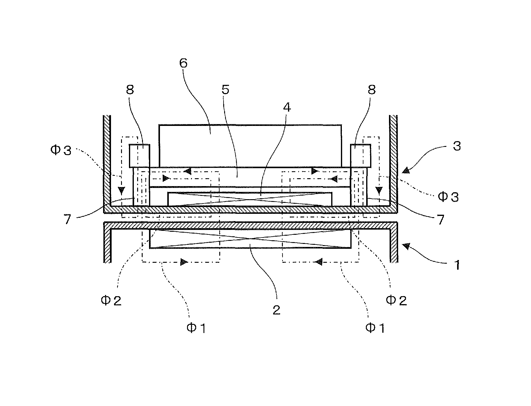
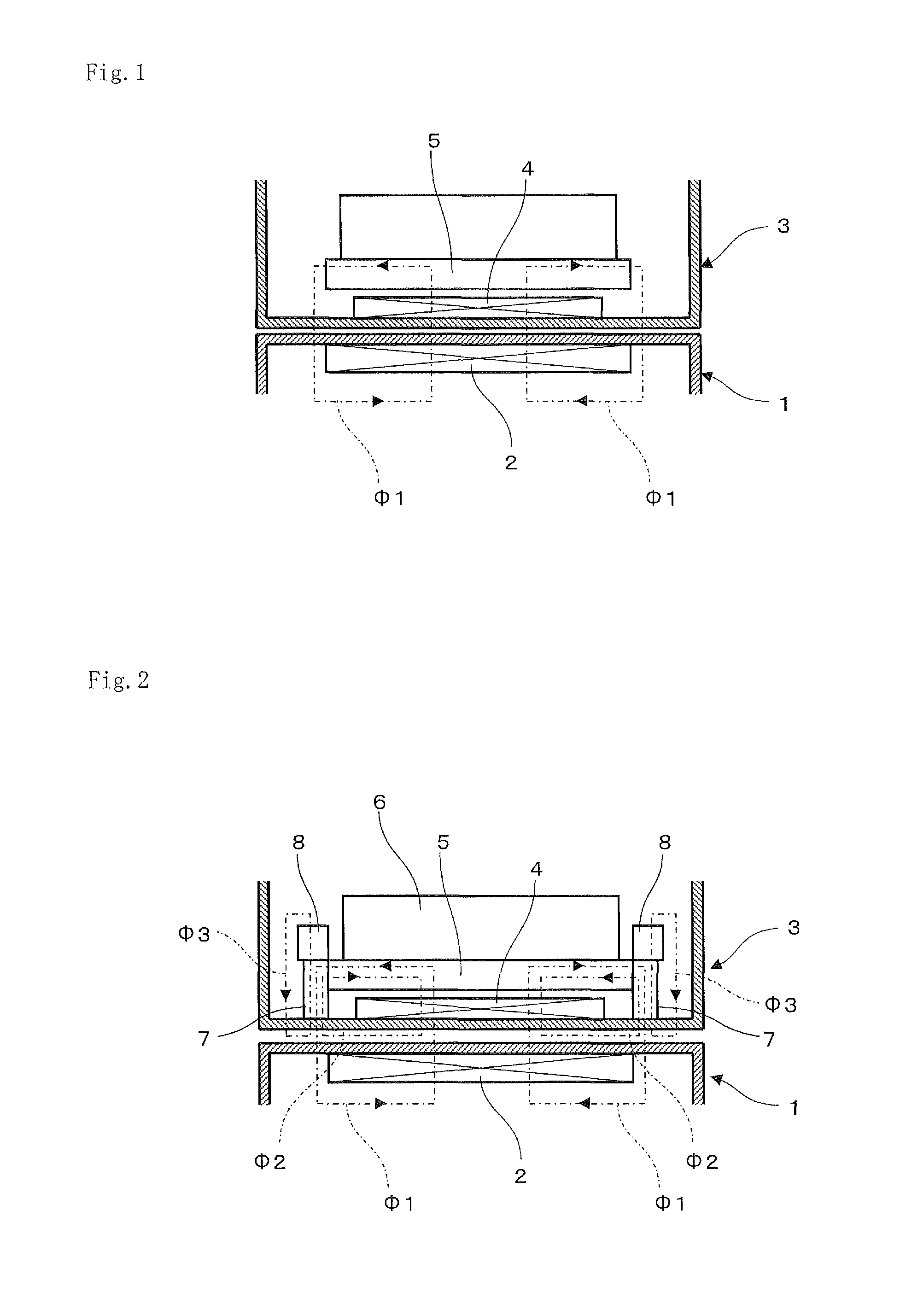
[0027]FIG. 2 is a partial schematic view showing a charger and a portable electronic device in a non-contact power transmission apparatus according to the exemplary embodiment of the present invention. FIG. 2 shows a state where the portable electronic device is mounted on the charger to be chargeable.

[0028]As shown in FIG. 2, the non-contact power transmission apparatus includes primary coil 2 disposed for power transmission in charger 1, and secondary coil 4 disposed for power reception in portable electronic device 3. Each of primary coil 2 and secondary coil 4 has an arbitrary surface surrounded with a conductor. Primary coil 2 and secondary coil 4 are arranged so that the arbitrary surfaces can face each other when portable electronic device 3 is mounted on charger 1.

[0029]Primary coil 2 is electrically con...


PUM

PropertyMeasurementUnit
magnetic fluxaaaaaaaaaa
saturated magnetic fluxaaaaaaaaaa
magnetic forceaaaaaaaaaa

Abstract

Provided is a non-contact power transmission apparatus that can be made thinner without any drop in power transmission efficiency.The non-contact power transmission apparatus includes: primary coil (2) generating a magnetic flux (Φ1); secondary coil (4) disposed facing primary coil (2) to receive power in a non-contact manner from primary coil (2) by electromagnetic induction; magnetic-substance layer (5) that covers a side opposite the side of secondary coil (4) facing primary coil (2) so that the magnetic flux (Φ1) can pass; magnet portion (7) disposed to be able to switch two magnetic poles and configured to generate a magnetic flux (Φ2) that is larger than the difference between the maximum value of the first magnetic flux (Φ1) and the saturated magnetic flux of magnetic-substance layer (5) and that passes through magnetic-substance layer (5) in a direction in which magnetic-substance layer (5) spreads; and magnetic pole switching unit (8) that detects the direction of the first magnetic flux (Φ1), and switches the magnetic pole of magnet portion (7) to generate a magnetic flux (Φ2) in a direction opposite the direction of the first magnetic flux (Φ1).

Description

TECHNICAL FIELD[0001]The present invention relates to a non-contact power transmission apparatus that transmits power in a non-contact manner. More particularly, the invention relates to a non-contact power transmission apparatus that can be miniaturized and made thin.BACKGROUND ART[0002]Recently, in portable electronic devices such as a portable telephone or an electronic information terminal, a secondary battery that can be discharged or charged, e.g., a lithium ion battery or a nickel hydride battery, is frequently used. The portable electronic device using the secondary battery includes a charging terminal in its body. The secondary battery is charged by connecting the terminal to a charger.[0003]The portable electronic device is ordinarily held near a user to be always ready for use. Accordingly, when the charging terminal is exposed from the body of the portable electronic device, there is a possibility that the user will touch the charging terminal and receive an electric sho...

Claims


Application Information

Patent Timeline
Patent Type & Authority Patents(United States)
IPC IPC(8): H01F38/14H02J5/00H01F27/36
CPCH01F38/14H02J5/005H01F27/365H02J7/00712H01F27/36H01F27/366H02J50/10H02J50/70
Inventor KIYOTA, ATSUSHI
Owner NEC CORP
Why Eureka
Try Eureka